EasyManuals Logo

Trane TR200 Series User Manual

Trane TR200 Series
295 pages
To Next Page IconTo Next Page
To Previous Page IconTo Previous Page
Page #44 background imageLoading...
Page #44 background image
130BP075.10
OR
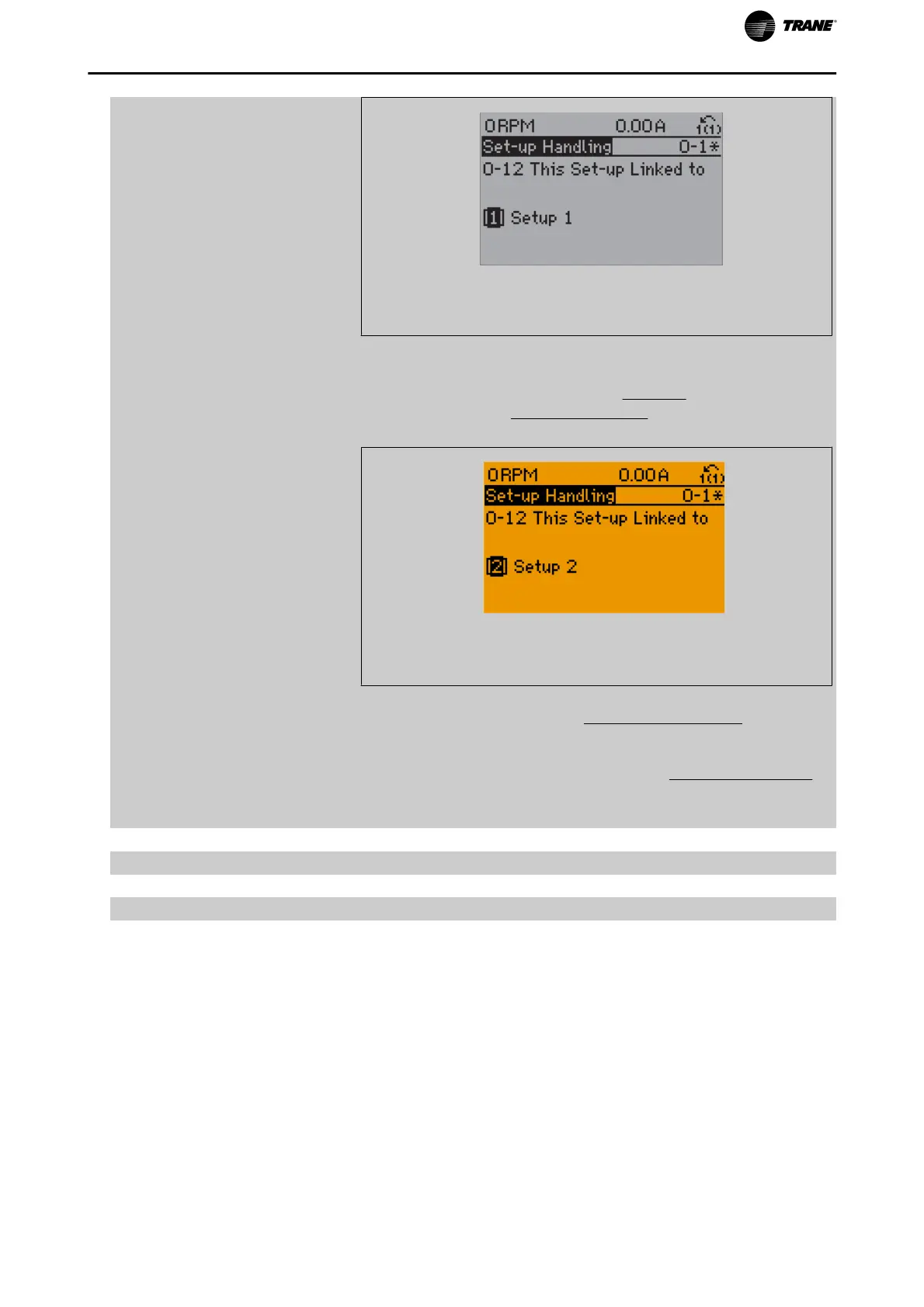
2. While still in Set-up 1, using par.0-50
LCP Copy, copy Set-up 1 to Set-
up 2. Then set par.0-12
This Set-up Linked to to
Set-up 2
[2]. This will start
the linking process.
130BP076.10
After the link is complete, par.0-13 Readout: Linked Set-ups will read {1,2}
to indicate that all ‘not changeable during operation’ parameters are now
the same in Set-up 1 and Set-up 2. If there are changes to a ‘not change-
able during operation’ parameter, e.g. par.1-30
Stator Resistance (Rs), in
Set-up 2, they will also be changed automatically in Set-up 1. A switch
between Set-up 1 and Set-up 2 during operation is now possible.
[0] * Not linked
[1] Set-up 1
[2] Set-up 2
[3] Set-up 3
[4] Set-up 4
Parameter Description
TR200 Programming Guide 43

Table of Contents

Other manuals for Trane TR200 Series

Questions and Answers:

Question and Answer IconNeed help?

Do you have a question about the Trane TR200 Series and is the answer not in the manual?

Trane TR200 Series Specifications

General IconGeneral
Input Voltage24 VAC
Frequency Range50/60 Hz
Communication ProtocolsBACnet MS/TP, Modbus RTU
Controller TypeProgrammable
Power Range20 VA
Control MethodPID Control
Enclosure RatingIP20
Operating Temperature32°F to 122°F (0°C to 50°C)
Humidity Range5% to 95% non-condensing
MemoryNon-volatile

Related product manuals