12 Tracer AdaptiView Display Operations Guide • CTV-SVU01B-EN
Introduction
Component Screens
Each chiller component has a touch target, accessible from the home screen, that is
illustrated in Figure 1, p. 7 (main display area/home screen) and described in Tab le 2,
p. 9. If you touch anywhere on the target, an additional screen appears that contains data
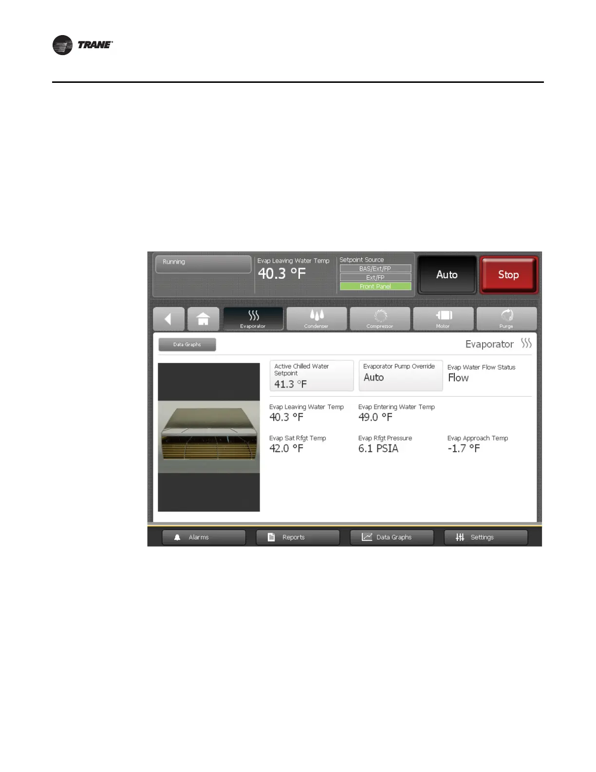
related to that component, as show in the example in Figure 3.
A graphic of the component is included on the left side of each component screen. If the
chiller is running, all graphics are animated except for the purge graphic.
“Appendix A: Component Screen Data,” p. 59 lists the settings and status points that are
available for each of the component screens. The chiller configuration determines which
of the settings and status points appear.
Some settings appear on this screen as buttons. These buttons take you to another
screen, where you can change the setting. (See, for example, the buttons on the
evaporator component screen in Figure 3, which show the Active Chilled Water Setpoint
and the Evaporator Water Pump Override).
Note: For more information about changing settings, see “Equipment Settings,” p. 34.
Figure 3. Component screen example (evaporator screen shown)
 Loading...


