Assembly and Disassembly
43-06955 - Rev Q Page 57
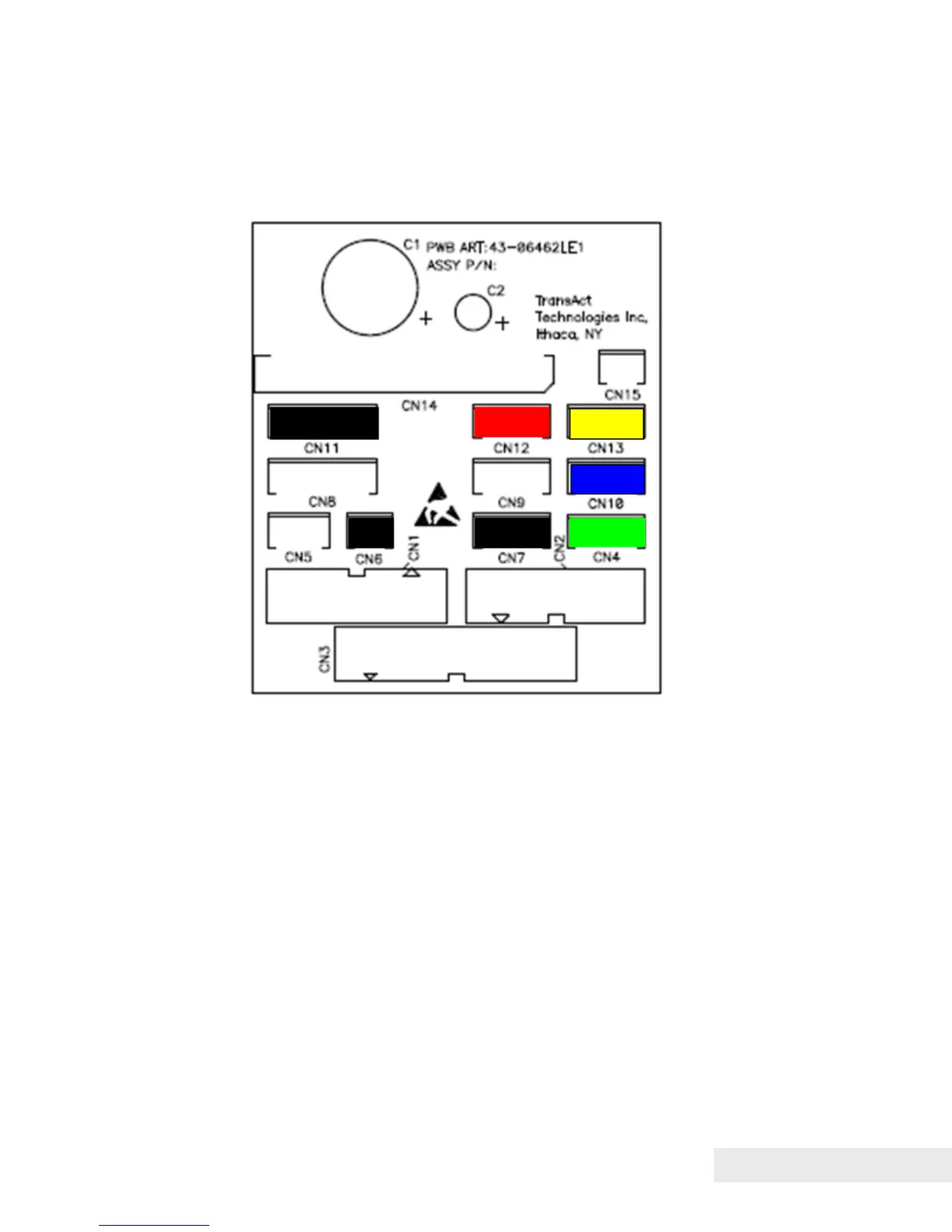
Electrical connections
Internal electrical connections terminating on the printed circuit board mounted
on the Right Side Frame Assembly are as follows:
Figure 21. Connectors on Right Side Assembly Printed Circuit Board.
Wiring harnesses connected to these ports generally have either a label or a
color-coded heat shrink wrap near their ends, as outlined in the following
table:
CONN. FUNC. COLOR
CN1 cntlr motors label
CN2 cntrl sensors label
CN3 cntrl head cable label
CN4 paper low sensor green
CN5 bezel lamp white
CN6 knife drive black
CN7 ticket taken sensor black
CN8 transport motor white
CN9 paper out sensor white
CN10 jam sensor blue
CN11 feed motor black
CN12 knife sensor red
CN13 TOF sensor yellow
CN14 mech head cable label
CN15 cover switch white