Assembly and Disassembly
Page 64 43-06955 - Rev Q
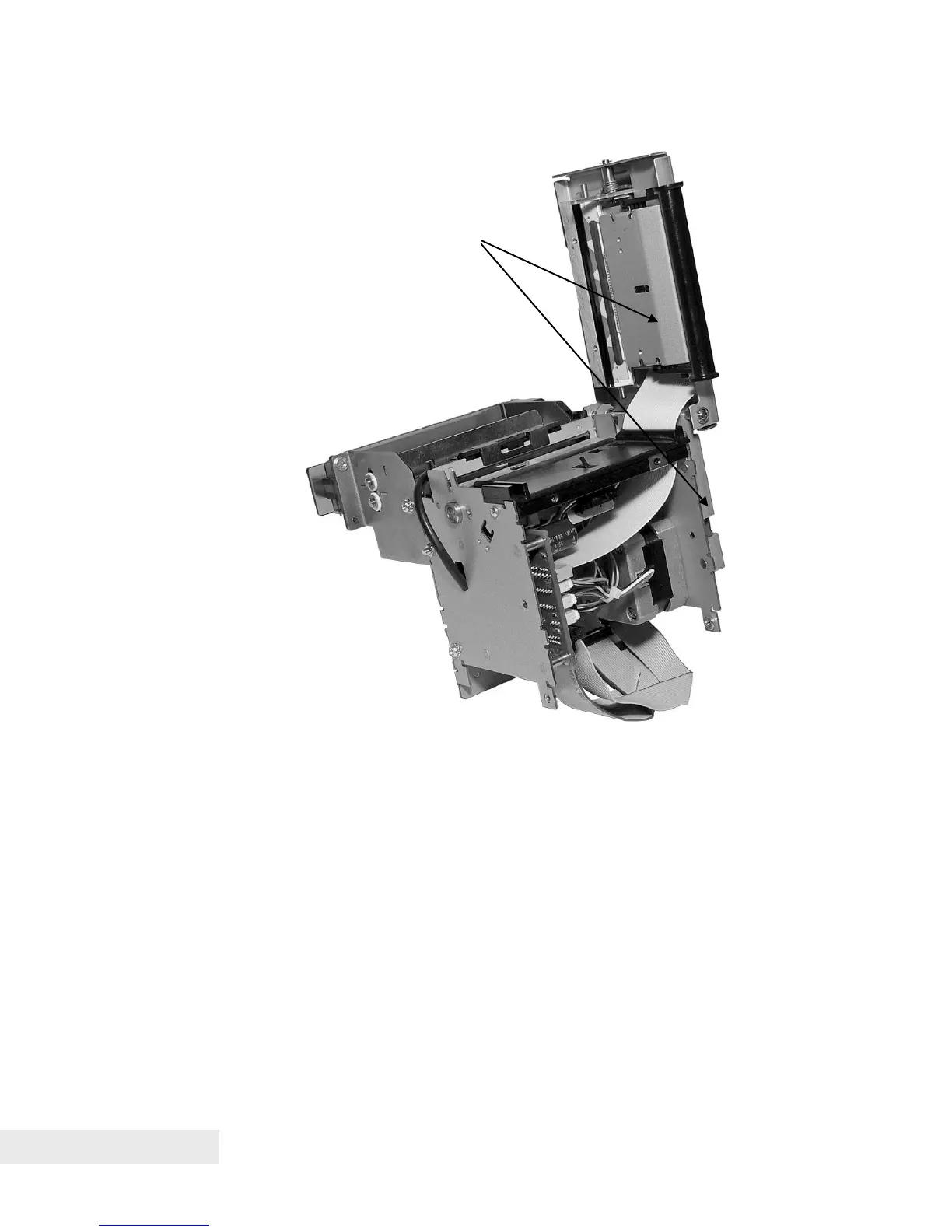
Figure 29. Top Cover Assembly and Left Side Assembly Attached to Printer Assembly
• Thread the ribbon cable from the print head through the hole in the bottom
paper guide.
• Aligning bearing of platen with hole in Right Side Assembly, and aligning
stripper pins with holes in left and right side plates, attach Left Side
Assembly and attached Top Cover Assemblies using M3 nuts to attach to
studs and M3 Sems screws to holes.
• Connect Print Head Cable to corresponding port on the Interconnect
printed circuit board
• Connect Feed Motor Harness to connector port CN11 (black).