Assembly and Disassembly
Page 62 43-06955 - Rev Q
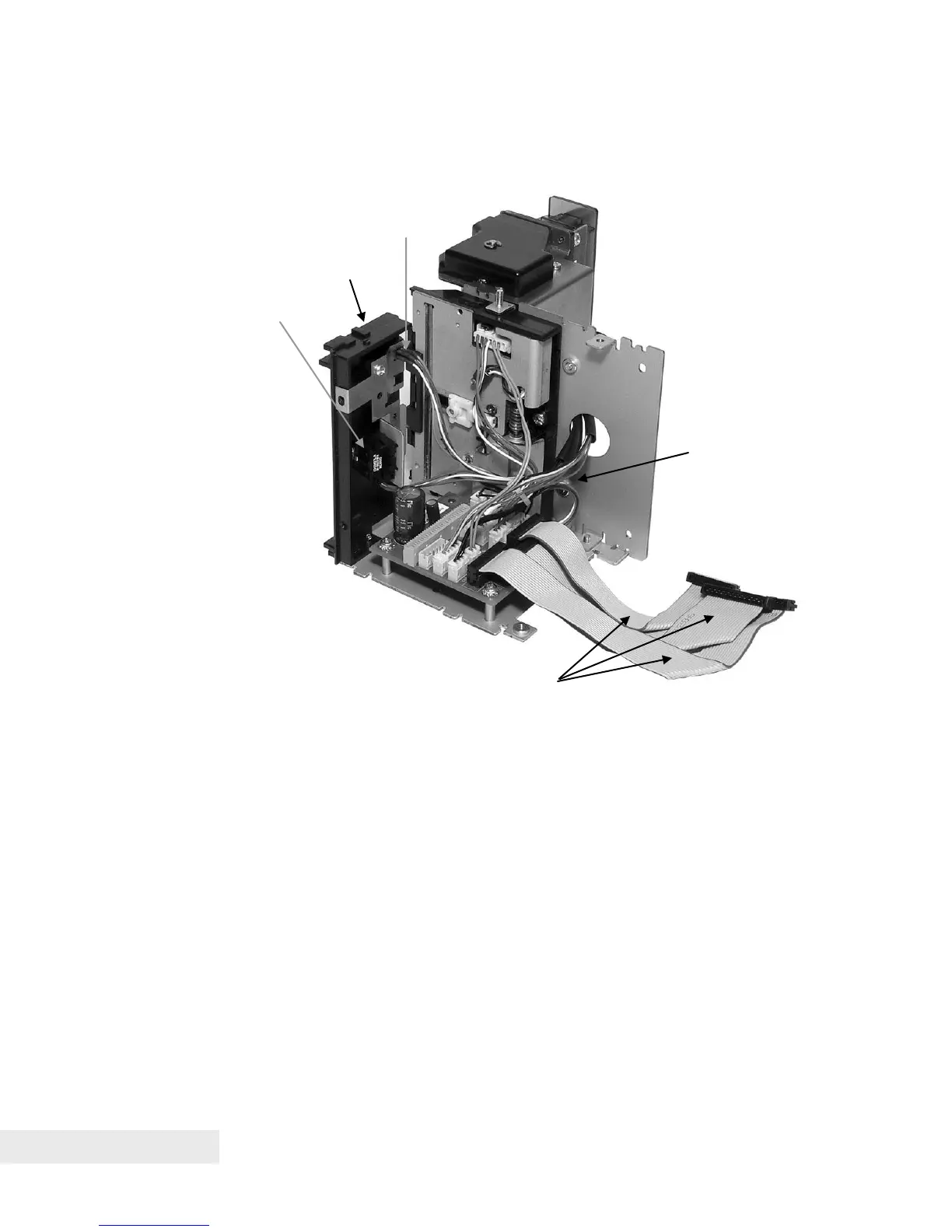
Step 5. Connect Paper Path Assembly
Figure 27. Connect Paper Path Assembly
• With the Paper Out and Top of Form sensors previously mounted to the
Bottom Paper Guide, attach the Bottom Paper Guide to the Right Side
Frame Assembly using a self-tapping plastic screw near the top edge of
the Right Side Frame Assembly.
• Connect the Paper Out wiring harness to connector CN9 (white) and the
Top of Form wiring harness to connector CN13 (yellow) on the Right Side
Assembly printed circuit board.
• Connect the Tie-Wrap Bundles of wiring harnesses for remaining sensor
and motor connections to the appropriate color-coded locations on the
sensors, motors at one end, and the Right Side Frame Assembly printed
circuit board at the other end.
• Connect three Umbilical Cables to the connections shown on the Right
Side Assembly printed circuit board for the Print Head (CN3), Sensors
(CN2) and Motors (CN1).