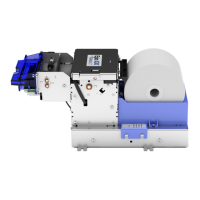
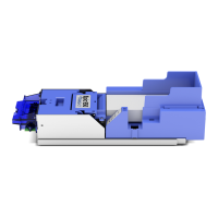
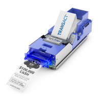
Assembly and Disassembly
Page 58 43-06955 - Rev Q
Assembling the Printer Mechanism
Step 1. Front Frame to Right Side Frame Assembly
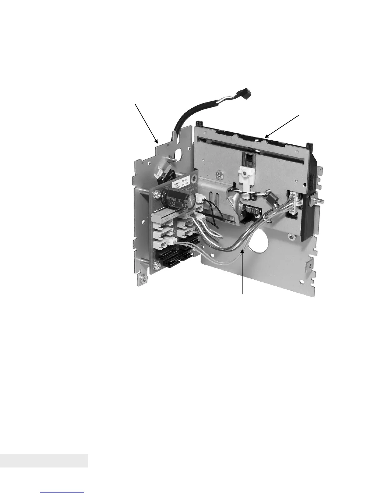
Figure 22. Attaching the Front Frame to the Right Side Frame Assembly.
• Connect the Front Frame Assembly to the Right Side Frame Assembly,
aligning the stud on the Front Frame Assembly with a corresponding hole
on the Right Side Frame Assembly. Fasten these two assemblies using an
M3 hex nut over this stud, as well as an M3 Sems screw for the other
threaded hole between the two assemblies.
• Connect the knife harness from the Knife Assembly to the printed circuit
board, hooking the 2-wire connection for the knife drive motor to connector
CN6 (black) and the 4-wire connection for the knife sensor to connector
CN12 (red), as shown in Figure 21. Note that the Jam Sensor will already
be installed and plugged into the PCB on the Right Side Frame Assembly.
Right side frame assembly