43-06955 - Rev Q Page vii
Figures
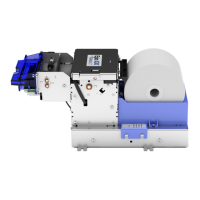
Figure 1. Epic 430
TM
Printer. ......................................................................... 11
Figure 2. Epic 430
TM
Dimensions. ................................................................. 13
Figure 3. Temperature and Humidity Ranges. ............................................... 14
Figure 4. Pin Functions for Power Input Connector. ...................................... 18
Figure 5. Location of TEST Button Inside Electronics Base. .......................... 22
Figure 6. Loading a Paper Roll. ..................................................................... 29
Figure 7. Electronics Base Assembly to Final Product ................................... 37
Figure 8. Optional Remote Base Cover ......................................................... 38
Figure 9. Remote Base Mounted to Printer Mechanism................................. 39
Figure 10. Custom Bezel Mounting and Hardware Requirements ................. 40
Figure 11. Sensor Breakdown and Locations. ............................................... 43
Figure 12. Communication PCB Location and Connector Info. ...................... 47
Figure 13. Power and Communications Cable Connections. ......................... 51
Figure 14. Exploded View of Main Assemblies for Epic 430 Printer. .............. 52
Figure 15. Right Side Frame Assembly. ........................................................ 53
Figure 16. Left Side Frame Assembly. .......................................................... 54
Figure 17. Front Frame Subassembly. .......................................................... 54
Figure 18. Transport Subassembly. ............................................................... 55
Figure 19. Paper Path Subassembly. ............................................................ 55
Figure 20. Top Cover Subassembly. ............................................................. 56
Figure 21. Connectors on Right Side Assembly Printed Circuit Board. .......... 57
Figure 22. Attaching the Front Frame to the Right Side Frame Assembly. ..... 58
Figure 23. Bezel Assembly and Electrical Harness ....................................... 59
Figure 24. Bezel Assembly Attached to Transport Assembly ......................... 59
Figure 25. Connect Transport Assembly ....................................................... 60
Figure 26. Connect Jam Sensor Assembly .................................................... 61
Figure 27. Connect Paper Path Assembly ..................................................... 62
Figure 28. Top Cover Assembly Attached to Left Side Assembly .................. 63
Figure 29. Top Cover Assembly and Left Side Assembly Attached to Printer
Assembly ............................................................................................... 64
Figure 30. Attaching Rear Plate to Printer Mechanism .................................. 65
Figure 31. Connect Umbilical Cables to Electronic Base PCB ....................... 65
Figure 32. Attach Printer Mechanism to Electronics Base ............................. 66
Figure 33. Attach Paper Bucket ..................................................................... 67
Figure 34. Base Plate and Paper Spindle for Remote Mounting Applications 68
Tables
Table 1 Serial Interface Pin-outs ................................................................... 17