Enkapsis & EnerSure Platform Installation Guide Rev07.2
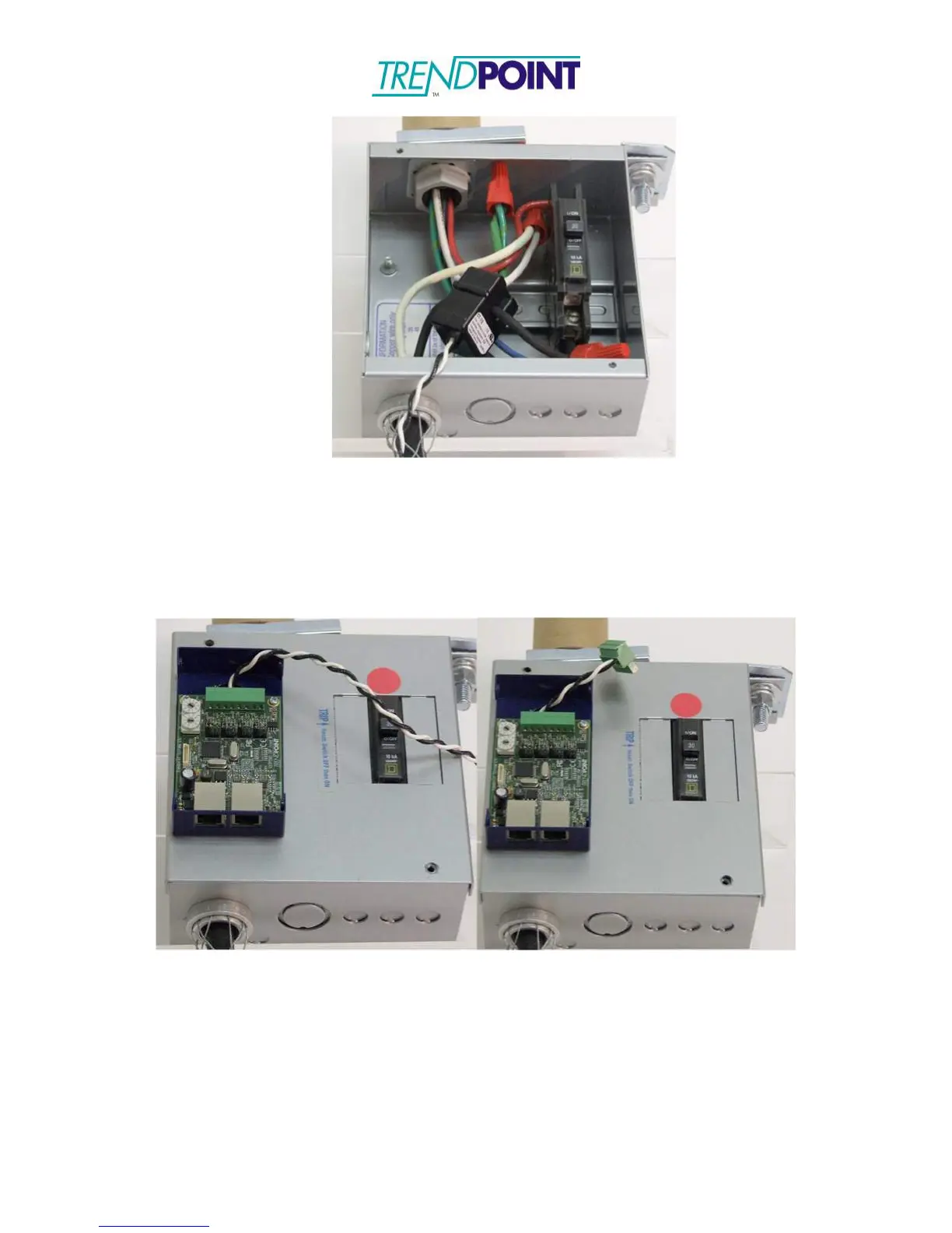
Figure 23: CT Connected to Circuit
3.) Feed the CT wires through the Bus Tap Card feed-though and connect to the 8- way
connector on the Bus Tap Card. The CT wires may be cut to length. (See CT
Wiring and Jumper Positioning for CT and connector order.)
Note: Connectors may be used to allow the Bus Tap Case to be completely
removed without unsnapping the CT’s.
Figure 24: CT wires fed through the Bus Tap Card, cut to length and connected
to CT connector
4.) Set the Phase Selection jumper for the CT. This tells the EnerSure Bus which phase
of power the CT is monitoring to allow for an accurate PF, Wattage, and kWh
reading.
5.) When all CT connections have been made the Bus Tap Card needs to be addressed.
To address the card use the 10 position selector switches on the card.