2-2
Remove the electronics assembly from the cabinet prior to cutting conduit openings in the cabinet
or mounting it to the wall.
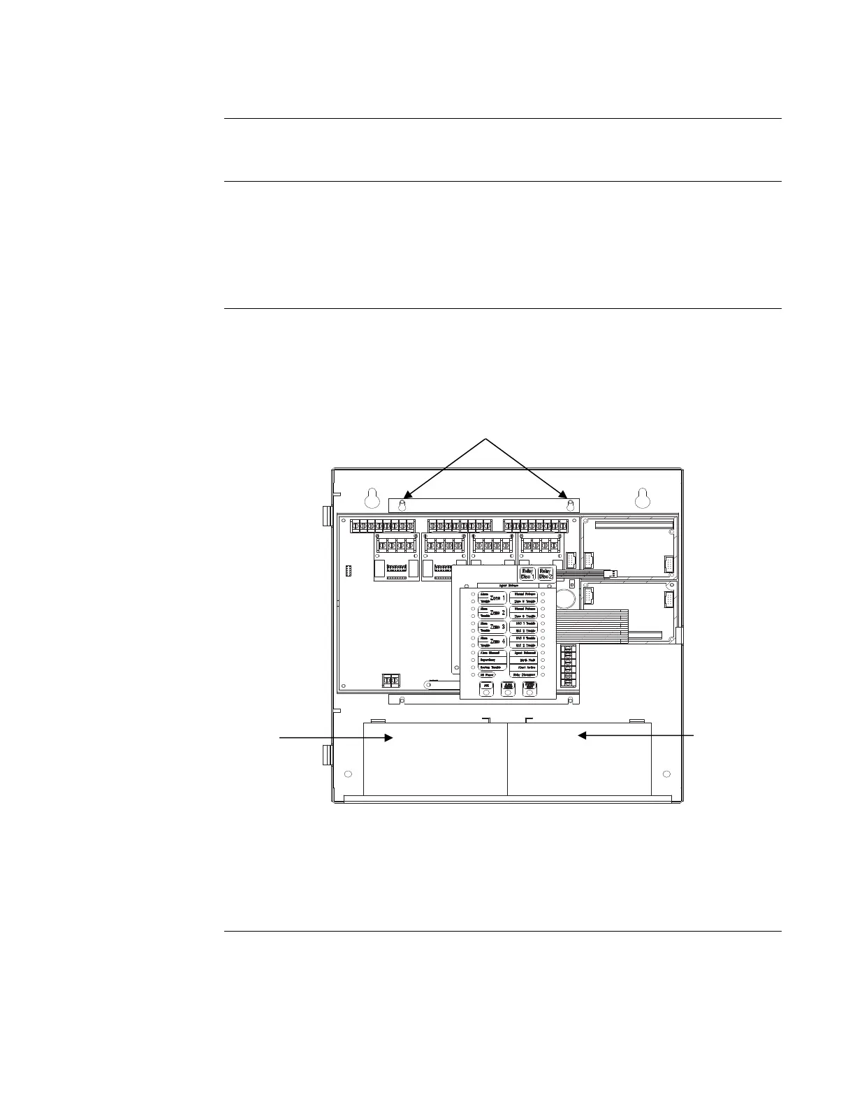
Figure 2-1 shows the locations of the four mounting screws used to secure the electronics assembly
to the AutoPulse Z-10 cabinet. To remove the assembly from the cabinet, loosen the four T15
Torx screws indicated in the figure. Slide the entire electronics assembly up until the screws
located on the top of the assembly are in the cutouts of the teardrop holes. Tilt the top of the
electronics assembly out from the box until the teardrop holes on the top of the assembly clear the
screws and then lift the assembly straight up to remove it.
When installing the electronics assembly, place the assembly in the box so that the screws located
near the top of the box fit through the cutouts of the teardrop holes. Align the U shaped slots on
the bottom of the assembly with the screws located on the bottom of the box. Slide the electronics
assembly down and then tighten the four screws.
Figure 2-1. Location of Electronic Assembly Mounting Screws
10-4-01
Removing/Installing the Electronics Assembly
Introduction
Removing
Electronics
Assembly
Installing
Electronics
Assembly
T15 Slotted Torx Screw
T15 Slotted Torx Screw
T15 Slotted Torx Screw

 Loading...
