3-6
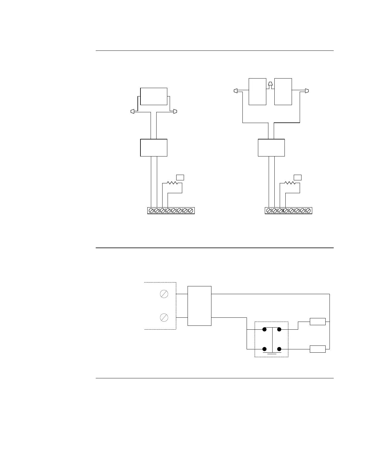
Field wiring connections between the releasing appliances and the panel’s RACs are made as
shown in the following figure. The coil supervision module provides polarization of the actuators.
Figure 3-2. Releasing Appliance Circuit (RAC) Wiring – Style Y (Class B)
Figure 3-3 shows wiring for a Part No. 76496 (surface-mount) or Part No. 76497 (flush-mount)
main/reserve switch. The main/reserve switch is rated for 1.1A make/break current at 28 VDC or
6A continuous carry current at 28 VDC. Locate the Part No. 430687 coil supervision module in
valve junction box.
Figure 3-3. Main/Reserve Switch
RAC1 RAC2
RAC1 +
RAC1 -
+
-
+
-
+
-
+
-
NAC1 NAC2
RAC2 +
RAC2 -
10K 1/2 W
(431222)
24 V
Actuator
5
YEL BLK
Coil
Supervision
Module
RED
BLK BLK
YEL
1 24V Unit
Per Circuit
RAC1 RAC2
RAC1 +
RAC1 -
+
-
+
-
+
-
+
-
NAC1 NAC2
RAC2 +
RAC2 -
10K 1/2 W
(431222)
12 V
Actuator
5
Coil
Supervision
Module
RED
BLK
2 12V Units
Per Circuit
12 V
Actuator
430687
Locate in
Valve
Junction
Box
430687
Locate in
Valve
Junction
Box
BLK
YEL
Connect to Release Appliance
Circuit (RAC) on System Board
(+) and (-) Designations
Correspond to the Alarm State
(+)
(-)
Coil
Supervision
Module
430687
Red
Blk
Blk
Yell
NO
NC
24VDC
Actuator
24VDC
Actuator
Key-Operated
Selector Switch
Wiring Releasing Circuits, Continued
Field Wiring
Connections
Main / Reserve
Switch

 Loading...
