3-5
The Releasing Appliance Circuits (RACs) on the AutoPulse Z-10 are designated on the printed
circuit board as RAC1 and RAC2. Each RAC must connect to a Part No. 430687 coil supervision
module, which in turn connects to two 12 VDC or one 24 VDC solenoid (also known as an
actuator).
Figure 3-2 shows the wiring connections to the AutoPulse Z-10.
All wiring must be 18 AWG (min.) to 12 AWG (max.).
Conductors must test free of all grounds.
All wiring is supervised and power limited unless otherwise noted.
Wiring between Part No. 430687 coil supervision module (Yell/Black) is not power limited.
Refer to the Coil Supervision Module Wiring Instructions (431303).
Leave a 10K, 1/2 W (Part No. 431222) resistor across all unused RAC terminals.
Voltage rating – nominal 24 VDC, 0.5 V peak-to-peak ripple, maximum.
Total available current from main power supply is 3A. If auxiliary power is used, available
signal power is reduced accordingly.
Terminal designations “+” and “-” are for the alarm state.
Connect 24 VDC actuator as shown, only one 24 VDC actuator per RAC.
Connect 12 VDC actuator as shown, two units must be connected via a maximum of 20 feet
of wiring in conduit.
For specific actuator wiring instructions, refer to the manufacturer’s recommendations.
Only releasing devices meeting the following criteria may be used with the AUTOPULSE
Z-10:
Releasing devices specified by part number in Table B-2 of this manual.
Releasing devices in FM categories A, B, C, D, E, F, G and H.
Max. alarm current is 2A per circuit. See following chart for line distances.
RAC2 is used as NAC3 (visual notification appliances) for the New York City Abort
application.
When RAC wiring is routed outside the building, use Listed Secondary Protector 430685. A
protector must be installed at the building entrance such that protected wiring is segregated
from unprotected (outdoor) wiring.
Maximum open circuit voltage, non-alarm (standby) state is 29 VDC. Maximum voltage,
alarm state is 26 VDC. Maximum current: 2 ADC.
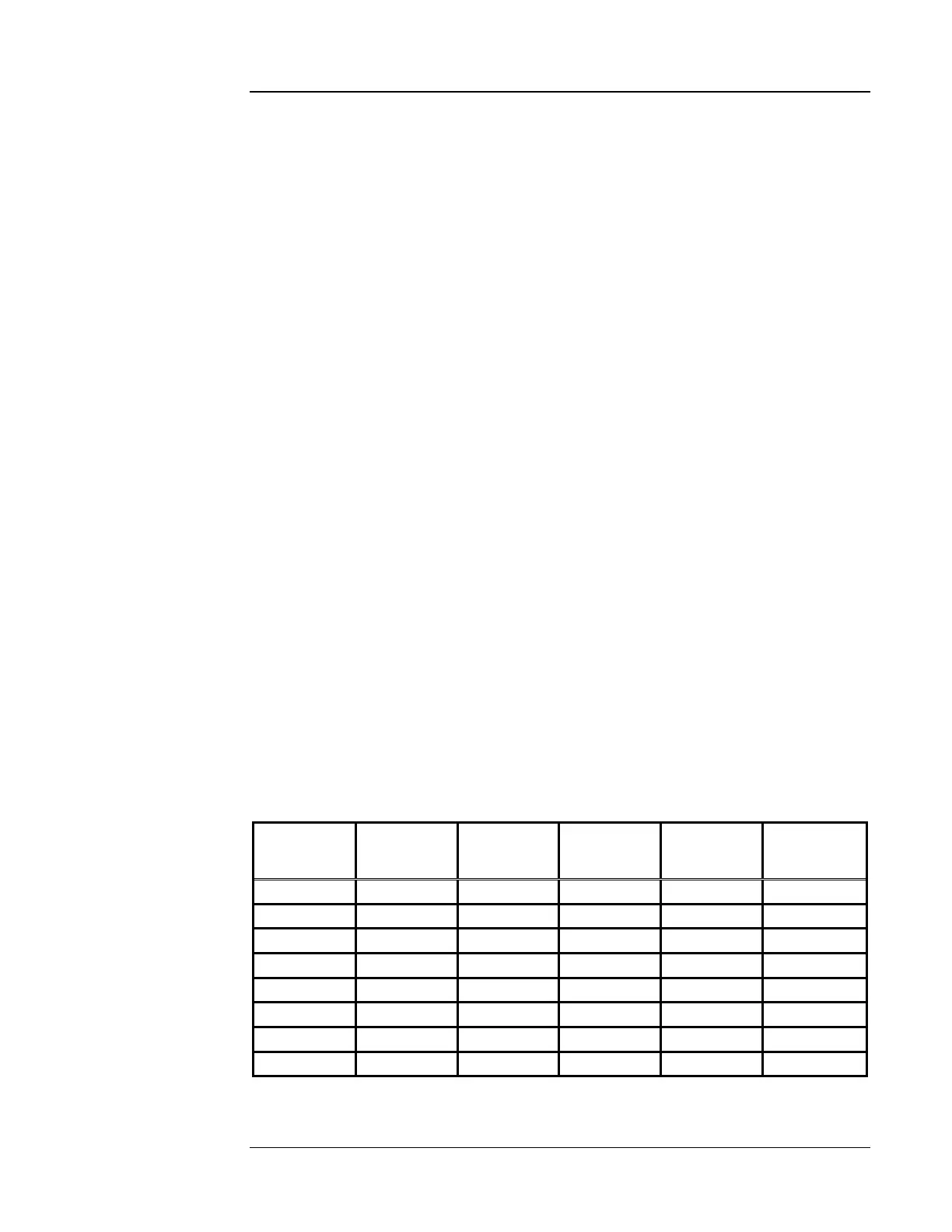
Table 3-1. Maximum Distance from Panel to Releasing Device (Feet)
Note: When RAC wiring is routed outside the building, use Listed Secondary Protector 430685. A protector
must be installed at the building entrance such that protected wiring is segregated from unprotected (outdoor)
wiring.
Wiring Releasing Circuits
Guidelines
Alarm
Current
(Amps)
18 AWG 16 AWG 14 AWG 12 AWG
Line
Resistance
(Ohms)
0.25 434 690 1098 1747 6.2
0.50 217 345 549 874 3.1
0.75 145 230 366 582 2.07
1 109 172 275 437 1.55
1.25 87 138 220 349 1.24
1.50 72 115 183 291 1.03
1.75 62 99 157 250 0.89
2 54 86 137 218 0.77

 Loading...
