4-4
Step 2. Set Program Switch to ON. Open the cabinet door, remove the plastic PCB cover,
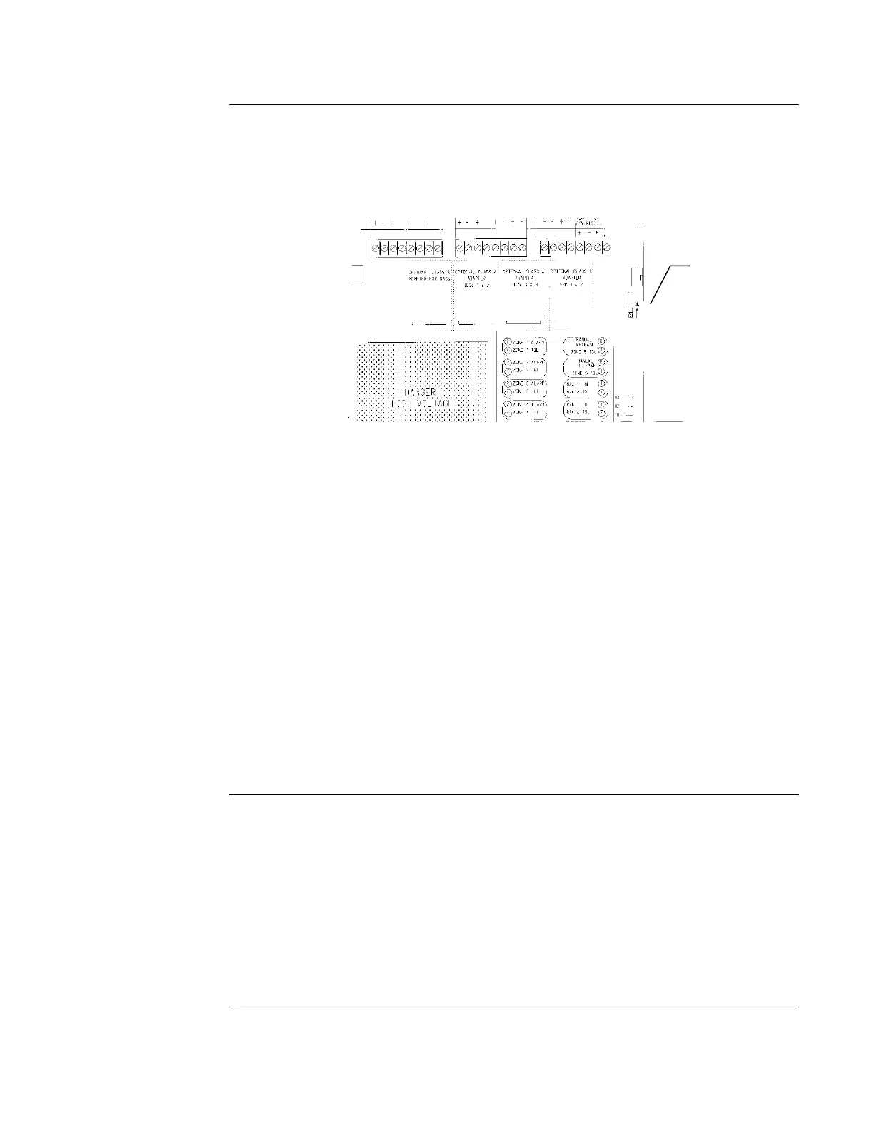
and set the Program Switch, located as shown in Figure 4-2, to the ON position. This places the
panel in programming mode. At this time, the tone-alert pulses and the Trouble LED flashes to
indicate a programming mode trouble. Pressing ACK silences the tone-alert and changes the LED
to steady ON.
Figure 4-2. Location of Program Switch
Step 3. Configure Terminal Emulator Serial Port Settings. Use a terminal emulation
program, such as Windows HyperTerminal, to establish a serial communication session with the
AutoPulse Z-10. Set the terminal emulator’s serial communication parameters as follows:
9600 baud
no parity
8 data bits
1 stop bit
Set Flow Control to None
Step 4. Enter a P at the Dash Prompt. A dash prompt appears in the terminal emulator
window to indicate that the PC and AutoPulse Z-10 are communicating with one another. Enter a
P at the dash prompt to start the programming session.
- P
The first prompt, which queries you for the application mode you want to select, automatically
appears when you type P. Refer to “Programming the Application Mode” later in this chapter for
a description of the application mode prompt.
Programming the AutoPulse Z-10 from the front panel is an 11-step process. With this method,
the AutoPulse Z-10 uses the LEDs on the front of the panel to represent the available
programming options. The left column of LEDs represents which general programming option is
selected and the right column represents context-sensitive choices for the selected programming
option. The System Reset key allows you to move down through the choices and the ACK key is
used to accept a selection and move to the next programming step. (The Alarm Silence key has no
programming function.)
Figure 4-3 summarizes the operation of the front panel programming method. When you place the
Program Switch in the ON position, the panel immediately enters programming mode and the
LEDs appear as shown in “1 – Application Mode.”
Overview, Continued
Text-Based
Programming
Front Panel
Programming
Location of
Programming
Switch. Place
switch in UP
position to turn
programming mode
on.
 Loading...

