3-4
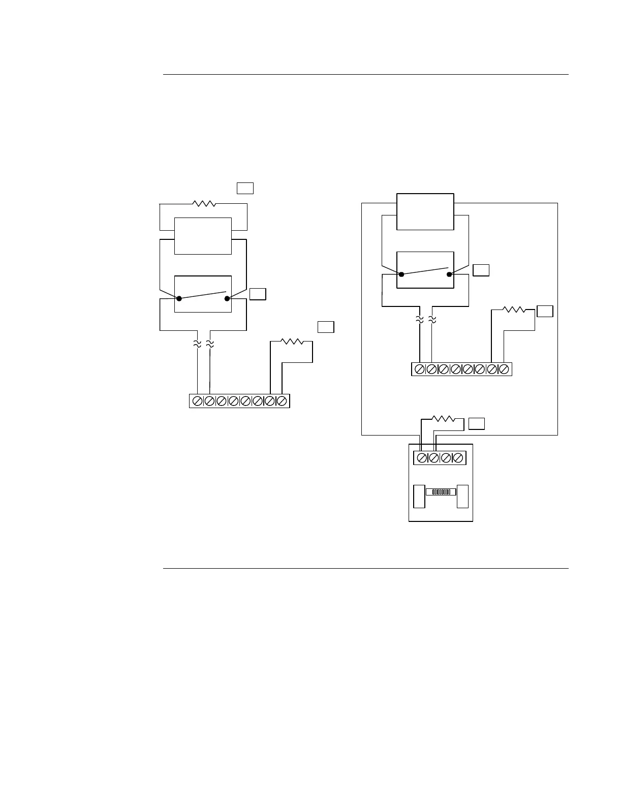
Field wiring connections between two-wire IDCs and the panel are made as shown in the
following figure. Refer to “Guidelines” earlier in this section for a list of compatible devices and
their installation instructions. If using contact closure devices, place device directly across
terminals with no current limiting resistor.
Figure 3-1. Two-Wire IDC Wiring
TB2
IDC1 IDC2
+1CDI
-1CDI
+
-
+
-
+
-
+
-
IDC3 IDC4
+4CDI
-4CDI
3.3K 1/2 W
3.3K 1W (431210)
Typical
Initiating
Device
STYLE B (CLASS B)
TB2
IDC1 IDC2
+1CDI
-1CDI
+
-
+
-
+
-
+
-
IDC3 IDC4
+4CDI
-4CDI
STYLE D (CLASS A)
+
-
+
-
Class A Adapter
IDC1 IDC2
3.3K 1W (431210)
6
4
5
4
3.3K 1/2 W
Contact Closure
Device
Typical
Initiating
Device
Contact Closure
Device
8
8
Wiring Initiating Device Circuits, Continued
Field Wiring
Connections –
Two Wire IDCs
 Loading...

