5. Secure the cable to/from the heating/cooling relay with a cable
clamp in the enclosure.
6. Close and secure the lid to the optional connections
compartment.
Relay function
Heating is activated when the relay is open, and cooling is activated
when the relay is closed.
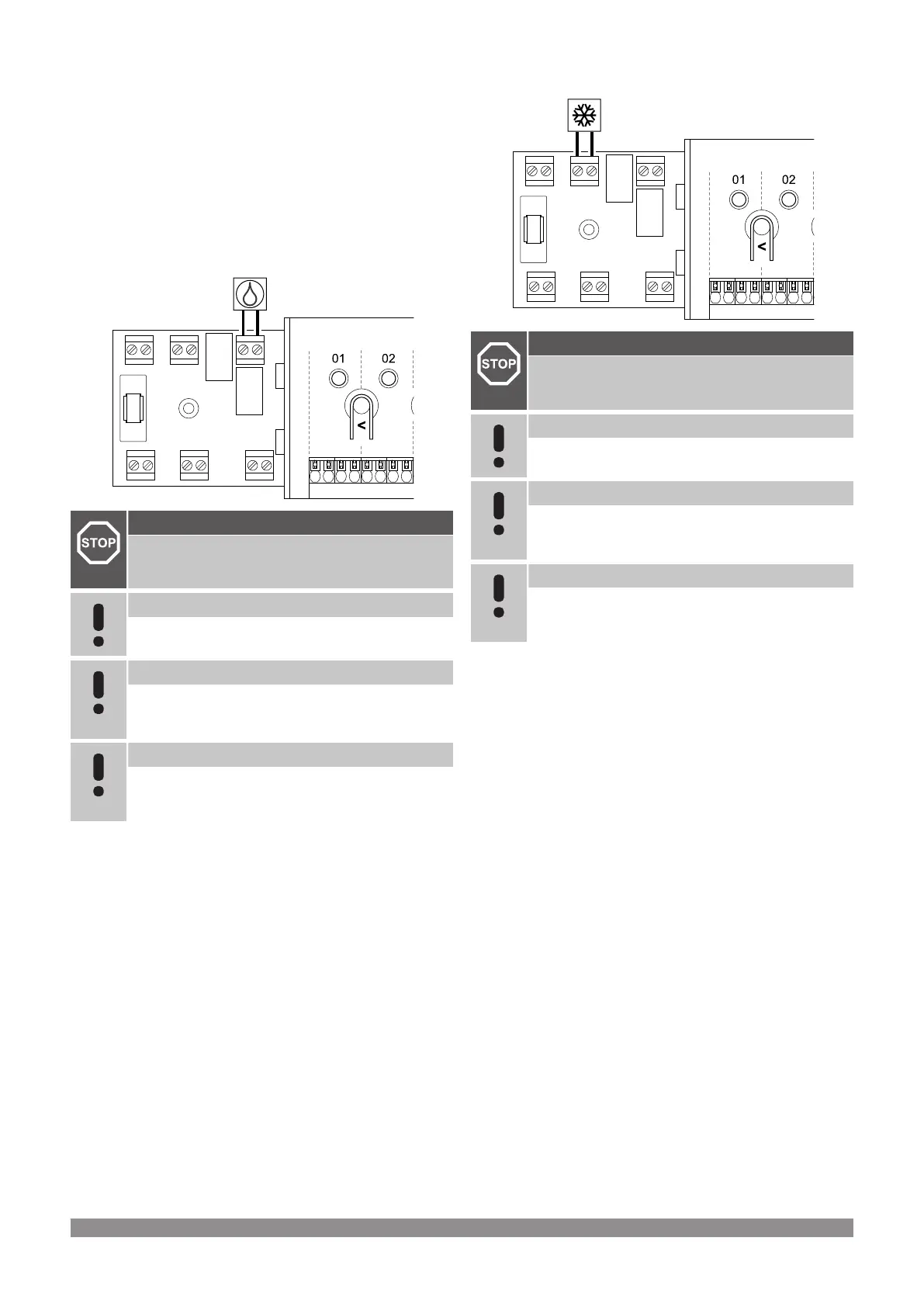
Dehumidifier (requires communication
module)
WD0000008
RELAY 2 (BOILER)
Warning!
Risk of electrical shock! Electrical installation and service
behind secured 230 V AC covers must be carried out
under the supervision of a qualified electrician.
Note
This connection requires a dry contact sensing input in
the dehumidifier.
Note
This relay function requires a communication module,
and must be set in Installer settings during initial
configuration, or in the System settings menu.
Note
In systems with a communication module, make sure that
room controller, relay 2 (Boiler), is set to Dehumidifier in
Installer settings.
1. Ensure that the power is disconnected from both the room
controller and the dehumidifier.
2. Remove the screw and open the cover for the optional
connections compartment.
3. Route the cable from/to the dehumidifier via a cable entry.
4. Connect the dehumidifier to the connection labelled Relay 2
(BOILER).
5. Secure the cable to/from the dehumidifier with a cable clamp in
the enclosure.
6. Close and secure the lid to the optional connections
compartment.
Relay function
The dehumidifier starts (relay closed) when the relative humidity
setpoint is reached when in cooling mode. It will stop when the
minimum run time of 30 minutes has finalized and when the relative
humidity has decreased below the defined RH setpoint - deadzone.
Chiller (requires communication module)
Warning!
Risk of electrical shock! Electrical installation and service
behind secured 230 V AC covers must be carried out
under the supervision of a qualified electrician.
Note
This connection requires a dry contact sensing input in
the chiller.
Note
This relay function requires a communication module,
and must be set in Installer settings during initial
configuration, or in the System settings menu.
Note
In systems with a communication module, make sure that
room controller, relay 1 (Pump), is set to Chiller in
Installer settings.
1. Ensure that the power is disconnected from both the room
controller and the chiller.
2. Remove the screw and open the cover for the optional
connections compartment.
3. Route the cable from/to the chiller via a cable entry.
4. Connect the chiller to the connection labelled Relay 1 (PUMP).
5. Secure the cable to/from the chiller with a cable clamp in the
enclosure.
6. Close and secure the lid to the optional connections
compartment.
Relay function
The chiller starts (relay closed) when there is a cooling demand while
in cooling mode. It will stop when the cooling demand is met.
Uponor Smatrix Base PULSE
|
Installation and operation manual
|
33