Relay function
The room controller start the circulation pump (relay closed) when
there is a demand for heating or cooling.
If a communication module is connected and multiple room
controllers are used the relay can be set to individal or common
pump mode.
Individual pump:
Relay function is set on a room controller basis. One circulation pump
per room controller is connected to relay 1. When there is a demand
to a specific room controller, only the pump connected to that room
controller is started.
Common pump:
Relay function is set on a system wide basis. One pump per system
is connected (to the master room controller relay 1 only). When there
is a demand somewhere in the system, the main pump is started.
When set to Common, the circulation pump relay can be used for
other functions on the sub room controller. See room controller relays
for more information.
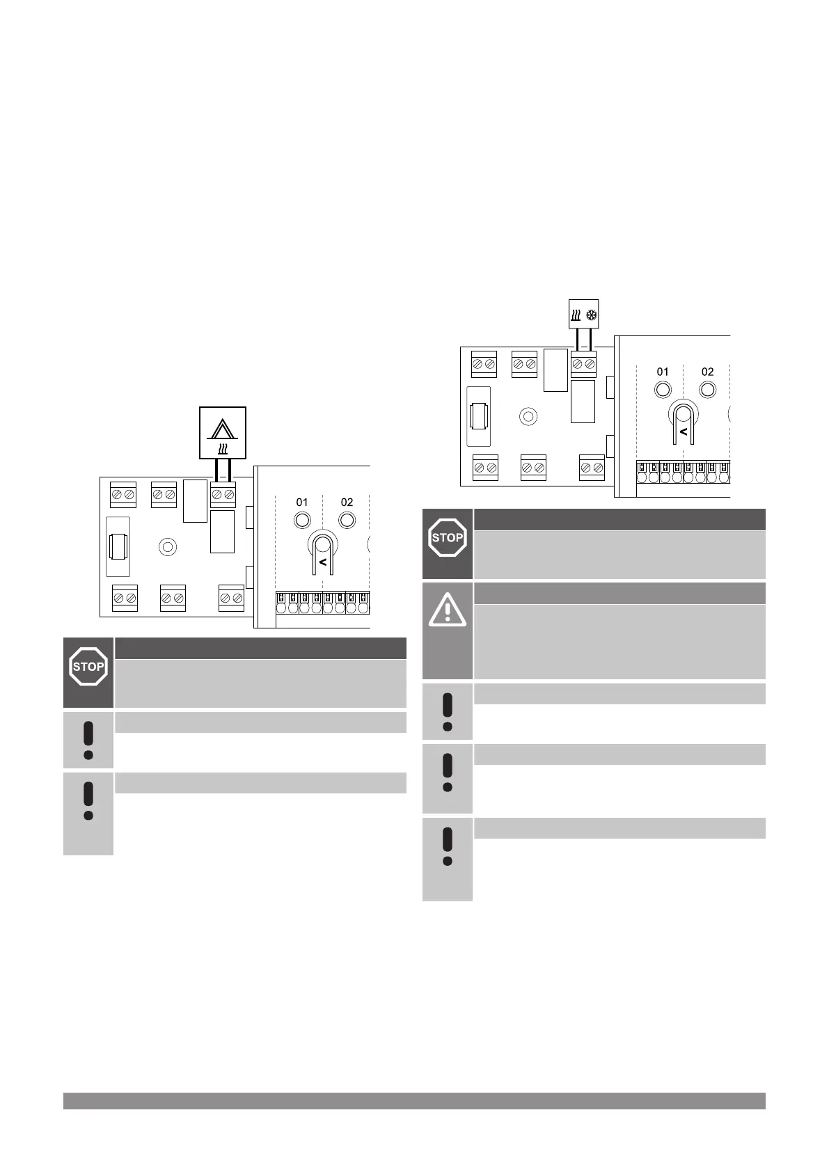
Boiler
RELAY 2 (BOILER)
WD0000004
Warning!
Risk of electrical shock! Electrical installation and service
behind secured 230 V AC covers must be carried out
under the supervision of a qualified electrician.
Note
This connection requires a dry contact sensing input in
the boiler.
Note
There is no power in the room controller to supply the
boiler. The boiler connector in the room controller
provides only a dry contact to switch on and off the power
connection to the boiler.
1. Ensure that the power is disconnected from both the room
controller and the boiler.
2. Remove the screw and open the cover for the optional
connections compartment.
3. Route the cable from/to the boiler via a cable entry.
4. Connect the boiler to the connection labelled Relay 2 (BOILER).
5. Secure the cable to/from the boiler with a cable clamp in the
enclosure.
6. Close and secure the lid to the optional connections
compartment.
Relay function
The boiler relay can be used to send a signal to either fire the heat
source, or to power open a 2-port motorised zone valve positioned on
the flow to the underfloor heating manifold. If the relay is used to
power open a zone valve then, the volt free auxiliary contacts on the
zone valve should be used to fire the heat source.
Alternatively, the boiler relay can be used to send a demand signal to
an electrically operated water temperature room controller. The
additional contacts on the water temperature controller should then
be used to fire the heat source.
The boiler is activated when the relay is closed.
Heating/cooling (requires communication
module)
WD0000005
RELAY 2 (BOILER)
Warning!
Risk of electrical shock! Electrical installation and service
behind secured 230 V AC covers must be carried out
under the supervision of a qualified electrician.
Caution!
If more than one room controller is available in the
system, and the circulation pump settings in Installer
settings is set to Common. The connector on the other
room controllers can be used for heating/cooling output
signal.
Note
This connection requires a dry contact sensing input in
the component producing heating/cooling.
Note
This relay function requires a communication module,
and must be set in Installer settings during initial
configuration, or in the System settings menu.
Note
In systems with a communication module, make sure that
room controller, relay 2 (Boiler), is set to H/C Switch in
Installer settings and that cooling is available in the
system.
1. Ensure that the power is disconnected from both the room
controller and the heating/cooling relay.
2. Remove the screw and open the cover for the optional
connections compartment.
3. Route the cable from/to the heating/cooling relay via a cable
entry.
4. Connect the heating/cooling relay to the connection labelled
Relay 2 (BOILER).
32
|
Uponor Smatrix Base PULSE
|
Installation and operation manual