Uponor Smatrix Base T-145
During normal operation a discreet LED on the thermostat is lit for
about 60 seconds if there is a demand for heating or cooling.
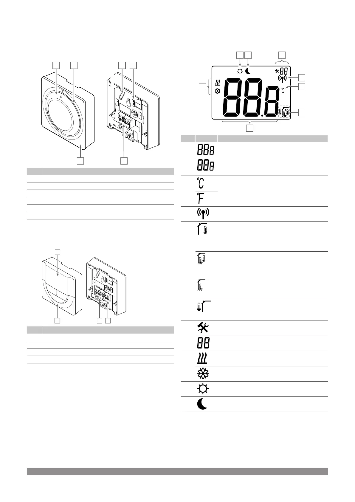
The illustration below shows the parts of the thermostat.
Item Description
A Room temperature setpoint dial control
B Heating/cooling demand LED
C Clear dial guide
D Registration button
E Disable timer switch
F Terminal for communication cable
Uponor Smatrix Base T-146
The illustration below shows the parts of the thermostat.
Item Description
A Display
B Buttons
C Terminal for external sensor (non-polarised)
D Terminal for communication cable
Display layout
The figure shows all possible symbols and characters that can be
shown on the display:
Item Icon Description
A Message field using three alphanumerical characters
Temperature reading using a - or + sign, two digital
characters, a decimal point and a character showing
either 0 or 5
B Temperature unit, shown when the character group A
shows a temperature
C Communication indicator
D Indoor temperature indicator
Remote sensor temperature indicator (RS mode)
The text Err and a flashing sensor icon indicates a
faulty sensor
Indoor temperature with floor temperature limitation
indicator
The text Err and a flashing floor sensor icon indicates
a faulty sensor
Floor temperature indicator
The text Err and a flashing floor sensor icon indicates
a faulty sensor
Outdoor temperature indicator
The text Err and a flashing outdoor sensor icon
indicates a faulty sensor
E Settings menu
Settings menu number
F Heating demand
Cooling demand
G Comfort mode
H ECO mode
68
|
Uponor Smatrix Base PULSE
|
Installation and operation manual