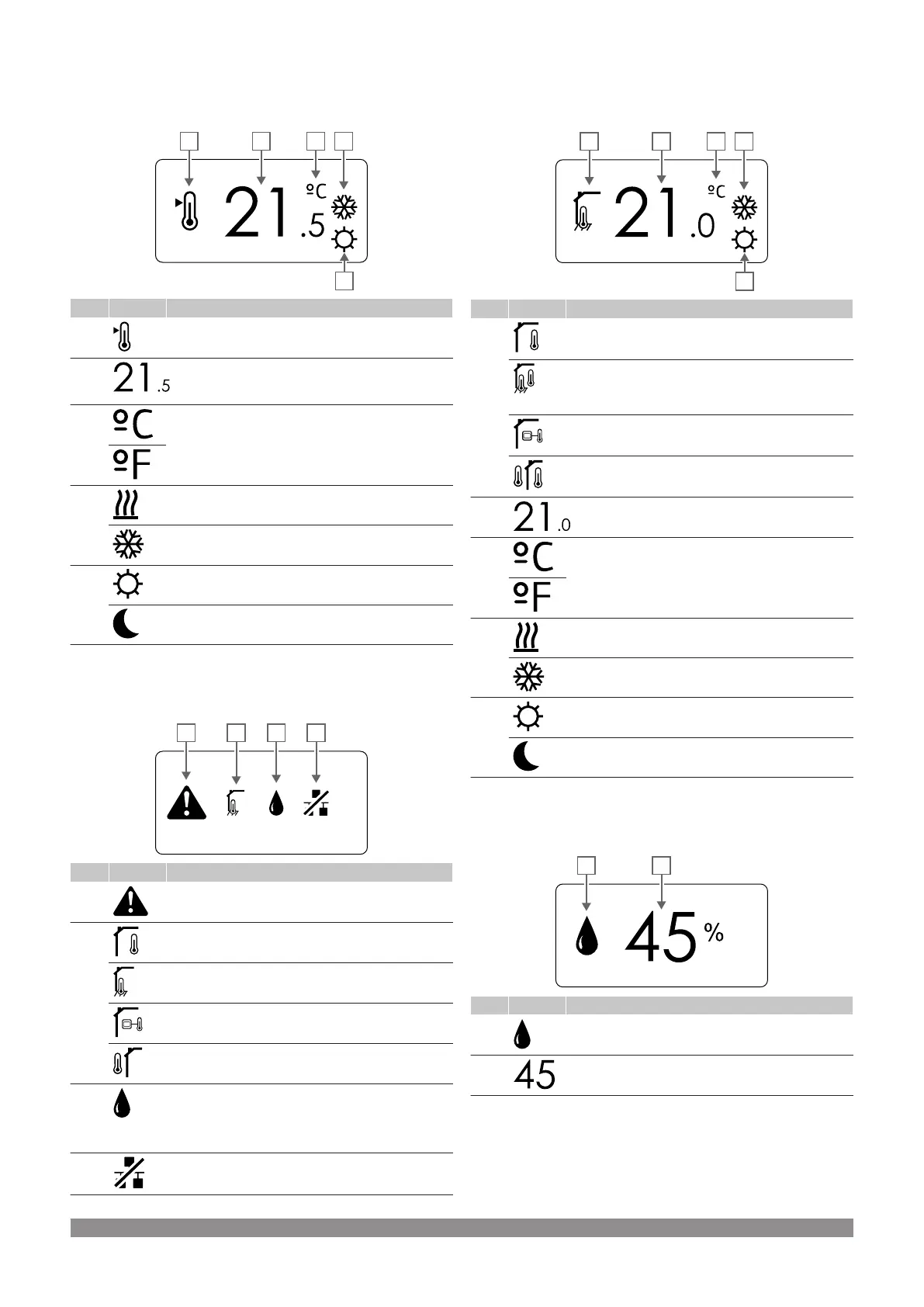
Change setpoint
The figure shows all possible symbols and characters that can be
shown on the display:
Item Icon Description
A Change setpoint mode
B Temperature setpoint, using a - or + sign, two digital
characters, a decimal point and a character showing
either 0 or 5
C Temperature unit
D Heating demand
Cooling demand
E Comfort mode
ECO mode
Alarms
The figure shows all possible symbols and characters that can be
shown on the display:
Item Icon Description
A Alarm mode
B Faulty indoor temperature sensor
Faulty floor temperature sensor
Faulty remote temperature sensor
Faulty outdoor temperature sensor
C Relative humidity limit reached (high limit)
This symbol is only shown if cooling is active, and if
RH control is be activated in Uponor Smatrix PULSE
app (requires communication module).
D Communication fault indicator
Control mode
The figure shows all possible symbols and characters that can be
shown on the display:
Item Icon Description
A Current control mode
Indoor temperature indicator
Current control mode
Indoor temperature with floor temperature limitation
indicator
Current control mode
Remote sensor temperature indicator
Current control mode
Outdoor temperature indicator
B Temperature unit, shown when the character group A
shows a temperature
C Temperature unit
D Heating demand
Cooling demand
E Comfort mode
ECO mode
Relative humidity
The figure shows all possible symbols and characters that can be
shown on the display:
Item Icon Description
A Relative humidity level
B Relative humidity reading using two digital characters.
Indicated with a “%” character
Uponor Smatrix Base PULSE
|
Installation and operation manual
|
71