M
ACHINE
P
REPARATION
& O
PERATION
Section
2.3
SB80 Work Platform - European 2-3
2.3 S
YSTEM
F
UNCTION
I
NSPECTION
NOTE: Refer to Figure 2-2 for chassis and plat-
form control locations.
IMPORTANT: Before performing the System
Function Inspection be sure the axles are fully
extended. For axle extending instructions, refer
to “Extending and retracting Axles”.
1. Before performing the following tests, check area
around machine and overhead for obstructions,
holes, drop-offs, and debris.
2. Turn chassis key switch to chassis, and pull out
emergency stop switches at the chassis control
panel and at the platform control panel.
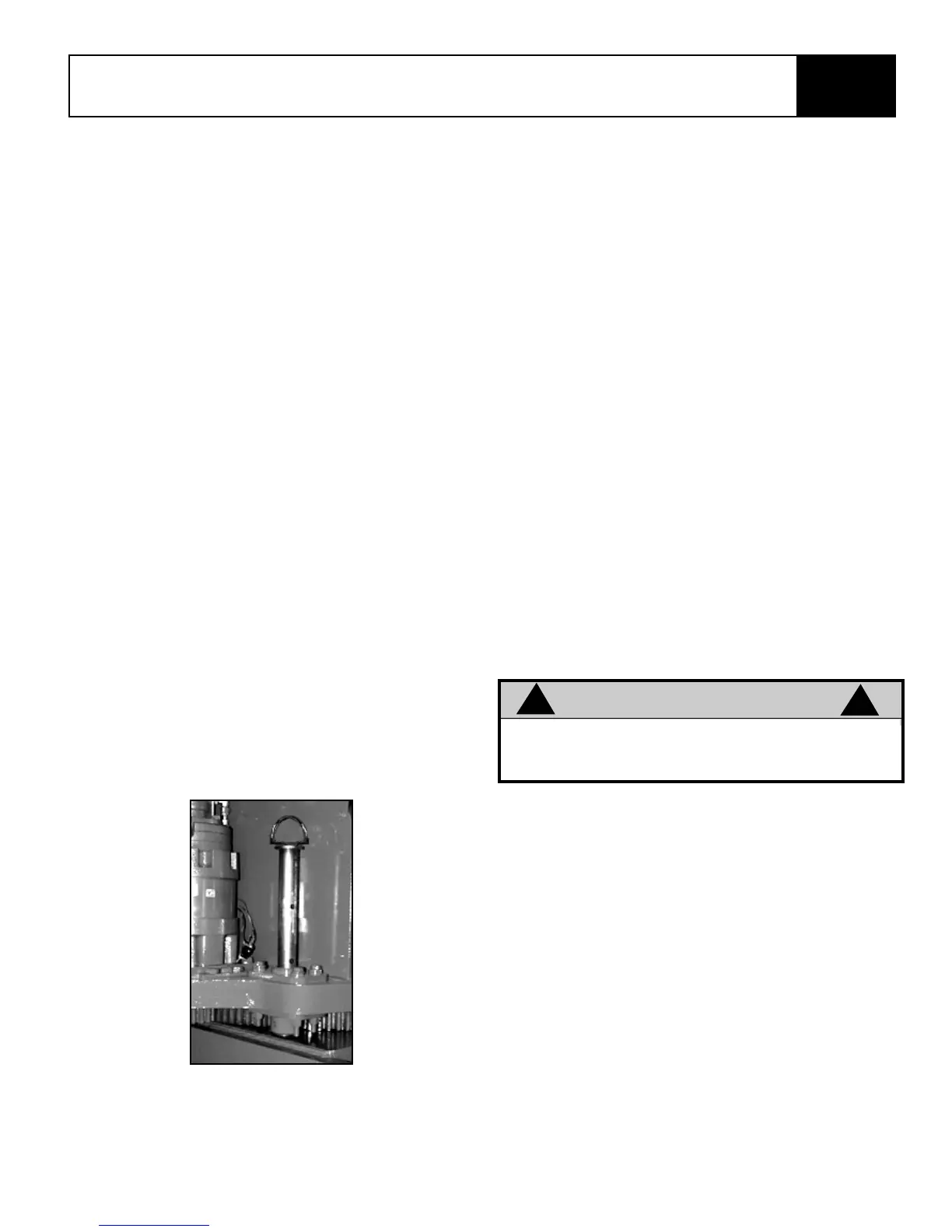
3. Retract locking pin (Figure 2-1).
4. Press the engine start toggle to crank the engine;
release when engine starts. If engine is cold (less
than 15 degrees F): press the glow plug button
and hold for six seconds prior to starting diesel
models.
5. Push in the chassis emergency stop button,
engine should stop. Repeat for platform emer-
gency stop button. Return both emergency stop
buttons to the on position, and start engine.
6. Operate function switches to raise / lower, rotate
left / right, each section of the elevating assembly
and observe the operation of the machine. All
functions should operate smoothly.
7. Turn chassis key switch to platform.
8. Mount the platform, and attach approved fall
restraint to designated platform anchorage point.
Attach only one fall restraint to each point.
Figure 2-1: Locking Pin
9. While depressing the foot switch, move the drive
control handle forward and reverse. Observe that
proportional functions operate smoothly, and that
brakes apply quickly after control is released.
10. While engaging the hand interlock, operate steer
switch to left and right. Observe that steering
wheels turn properly.
11. While depressing foot switch, operate boom con-
trols. Observe that boom operates smoothly, and
that boom raise and lower, turret rotation, and
boom extension and retraction operate propor-
tionally in conjunction with stroke of handle.
Observe that platform maintains level when boom
is elevated.
NOTE: Boom will not extend unless axles are
extended. Also boom will not raise beyond 45
12. With the boom elevated five degrees above hori-
zon or greater, operate drive control handle.
Observe that drive speed is limited to creep
(.30m [1 ft.] per second). Lower upper boom to
stowed position.
13. Press the service horn button. Observe that horn
is audible.
NOTE: Hand interlock controls drive/steer func-
tions only.
NOTE: Foot switch controls boom functions only.
WARNING
!
!
DO NOT use a machine that is damaged or
malfunctioning. Tag the machine and remove it
from service until it is repaired.