SB80 Work Platform - European 3-1
Section 3
M
AINTENANCE
3.1 I
NTRODUCTION
NOTE: For information on the engine refer to the
manual shipped with your machine.
This section contains instructions for the mainte-
nance of the Work Platform. Procedures for the oper-
ation inspection, adjustment, scheduled
maintenance, and repair/removal are included.
Referring to Section 2 will aid in understanding the
operation and function of the various components
and systems of the work platform, and help in diag-
nosing and repair of the machine.
Refer to Preventative Maintenance Checklist, for rec-
ommended maintenance intervals.
Ter m in ol o gy
TERMINAL BLOCKS: Located in upper and lower
control boxes. Designated by
TB##
. (##) designates
the number of the block which is written on the termi-
nal block. “R” right or “L” may follow the number.
WIRE COLOR: Indicated by
color/color
. First color
refers to insulation color and second color indicates
stripe color. If second color is not given there is no
stripe.
FORWARD: Front of machine indicated by yellow
arrows on chassis.
AFT: Rear of machine indicated by orange arrows.
GENERAL PROCEDURES
CONTACT BLOCKS: Removed by inserting a flat
screwdriver into the slot at either end of block and
prying outward. Installed by pressing into an empty
slot.
SWITCH MOUNT BASE: Assembled to back of
switch actuator. Removed by rotating the small black
lever counterclockwise and lifting off of base.
TERMINAL BLOCKS: Remove wires by inserting a
small flat bladed screwdriver into square beside wire.
Install wires by stripping 1.25 cm (1/2”) of insulation,
inserting screwdriver into square and inserting wire.
Be sure no strands are bent backwards. Replace
wires with same rating and type.
Special Tools
The following is a list of special tools which may be
required to perform certain maintenance procedures
on the work platform.
• 0-1000 PSI Hydraulic Pressure Gauge with
Adapter Fittings (014124-010)
• 0-3000 PSI Hydraulic Pressure Gauge with
Adapter Fittings (014124-030)
• 0-5000 PSI Hydraulic Pressure Gauge with
Adapter Fittings (014124-050)
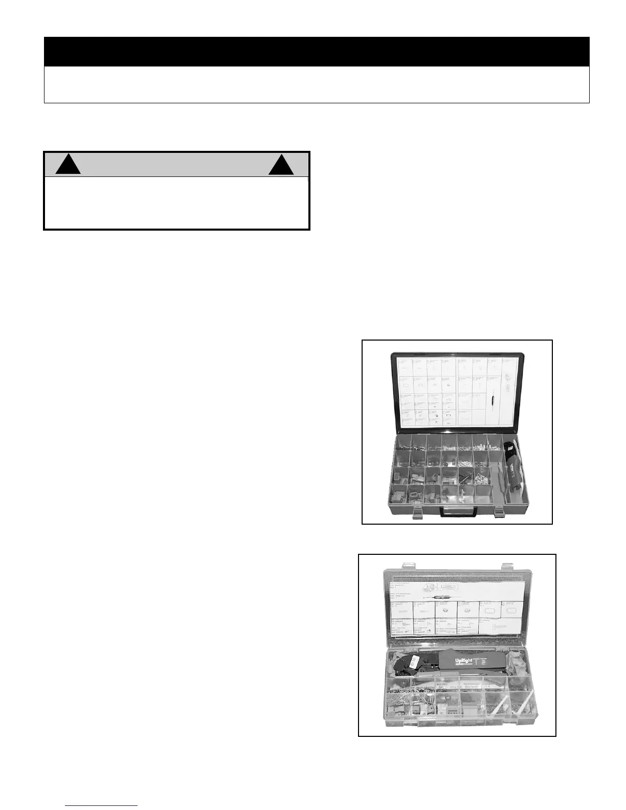
• Small Deutsch Connector Field Kit
(UpRight P/N 030899-000)
• Large Deutsch Connector Field Kit
(UpRight P/N 030898-000)
• Inclinometer
Figure 3-1: Deutsch Connector Kit, Large
Figure 3-2: Deutsch Connector Kit, Small
WARNING
!
!
Be sure to read, understand and follow all infor-
mation in the Operation Section of this manual
before attempting to operate or perform service
on any Work Platform.