3-18 SB80 Work Platform - European
M
AINTENANCE
Section
3.15
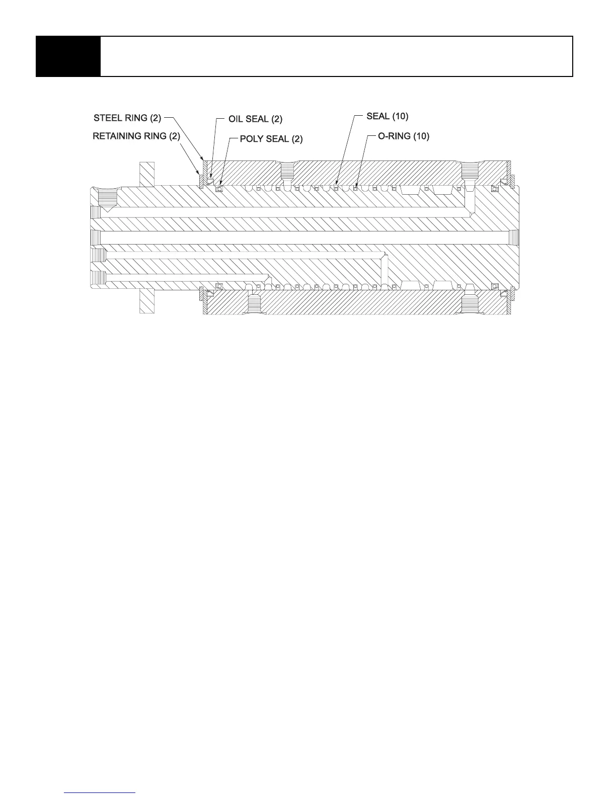
Figure 3-17: Rotary Manifold
3.15 R
OTARY
M
ANIFOLD
Removal
1. Mark and tag all hoses.
2. Remove all hoses from rotary manifold.
3. Remove rotary manifold from machine.
Disassembly
NOTE: Provide a clean work area for this opera-
tion, and observe clean assembly practices.
Seals and O-rings are highly sensitive to con-
tamination that may not be visible to the naked
eye.
1. Remove retaining rings from each end of rotary
manifold.
2. Carefully slide body out of housing.
3. Remove seal kit components.
4. Thoroughly clean all parts with solvent. Rinse the
inside of the tube and allow to drain. A high pres-
sure rinse and wipe with a lint free rag is prefera-
ble.
5. Inspect the body and housing for scratches, pits,
or polishing. Check seal groves and sealing sur-
faces. Scratches or pits deep enough to catch the
fingernail are unacceptable, replace the manifold.
Assembly
NOTE: Torque all hardware and fittings to torques
listed (see Table 3-2, page 28) unless other-
wise specified.
1. Lubricate all seals with clean hydraulic oil prior to
assembly.
2. Install new seals on body and housing.
3. Carefully slide body into housing.
4. Reinstall steel rings and retaining rings.
Installation
1. Installation is reverse of removal.
2. Replenish hydraulic fluid in tank.
3. Run hydraulic system for several minutes to
remove air from hydraulic lines. Cycle cylinders
for each boom function.
4. Rotate turret completely.
5. Check rotary manifold for leaks. Check that all
boom functions are operating properly.