SB80 Work Platform - European 3-15
M
AINTENANCE
Section
3.14
5. Remove primary sun gear (24) from end of input
shaft (2).
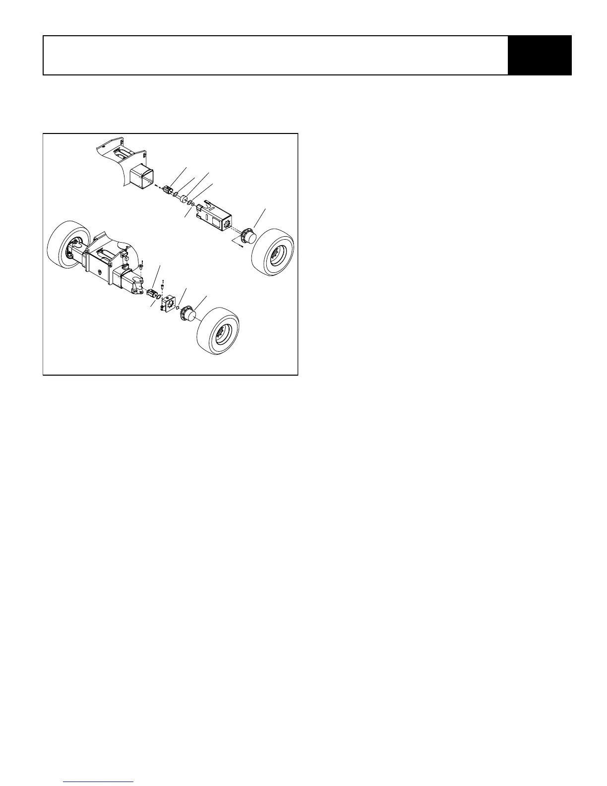
Figure 3-15: Torque Hub Assembly
6. Remove the primary carrier assembly (22).
7. Remove the secondary carrier assembly (21).
8. Remove the input shaft (2) from spindle (3).
Remove the retaining rings (17), washers (18),
and disengage spring (19) from input shaft (2)
only if replacement is required.
9. One tab of lock washer (15) will be engaged in
slot of bearing nut (16); bend back to release.
Remove the bearing nut (16), lock washer (15)
and thrust washer (14).
NOTE: A special locknut wrench is required for
the removal of the bearing locknut. The Bearing
Locknut Tool, Bearing Cone Driver and Spin-
dle/Shaft Drive Tool are included in Service Kit,
part number 100254-020.
10. Bolt Spindle Drive Tool, (Service Kit #100254-
020), to ring gear (20). Grade 8 bolts should be
used. Drive spindle (3) from hub (11) by turning
center bolt of Spindle Drive Tool. Care should be
taken to avoid damaging splines and threads on
spindle.
NOTE: Bearing cone (13) has been designed with
a press fit with respect to spindle (3). Consider-
able force will be required to remove cone from
spindle.
11. Remove Spindle Drive Tool from ring gear (20).
12. Remove the eighteen bolts (9) and washers (10)
from hub (11) and remove ring gear (20). It may
be necessary to strike ring gear (20) with a rub-
ber mallet to loosen from hub (11).
13. Remove the boot seal (4) and oil seal (5) and
bearing cones (6 & 13) from hub (11). Inspect
bearing cups (7 & 12) in position and remove only
if replacement is required.
Assembly of Torque Hub
1. Press new bearing cups (7 & 12) in each side of
the hub (11). It is recommended that bearing
cups (7 & 12) and cones (6 & 13) be replaced in
sets.
2. Assemble bearing cone (6) into cup (7) at seal
end of hub (11) and press a new seal (5) into hub
(11). Install boot seal (4) on hub (11) if unit is so
equipped.
3. Position spindle (3) upright on bench. Lubricate
lips of seal (5) and lower hub (11) onto spindle
(3). Hub (11) should be centered as it is lowered
over spindle (3) to prevent seal damage.
4. Assemble bearing cone (13) over spindle (3).
Press bearing cone (13) over spindle bearing
journal using press and cylindrical Bearing Cone
Driver (Service Kit #100254-020). Press bearing
cone (13) down until rollers just touch cup (12).
Take care to avoid pressing cone (13) to far.
NOTE: If a press is not available, place Bearing
Cone Driver tool over splined end of spindle (3)
on the edge of bearing cone (13) and drive into
place with hammer or mallet. If this method is
used, care must be taken to avoid damage to
bearing cone and spindle.
5. Install thrust washer (14) with tab in keyway of
spindle and bearing nut (16). DO NOT install lock
washer (15) at this time.
6. Clean mating surfaces and apply a bead of sili-
cone sealant to face of hub (11) that mates with
ring gear (20). See instructions on sealant pack-
age. Hub (11) is attached to ring gear (20) with 18
3/8-24 grade 8 hex head cap screws (9) and flat
washers (10). Torque cap screws to 70-81 Nm
(52-50 lb.-ft.).
7. Place Spindle Drive Tool (Service Kit #100254-
020), over spindle (3) and bolt or pin to ring gear
(20). Make sure center bolt of Drive Tool is not
touching spindle and is prevented from rotating
by jam nuts provided on tool.
Rear
Front
1
2
2
3
4
1
2
5
5
4
1. Motor
2. Gasket
3. Brake
4. Torque Hub
5. O-Ring