5-6 SB80 Work Platform - European
S
CHEMATICS
Section
5.3
5.3 H
YDRAULIC
S
CHEMATIC
, SB80
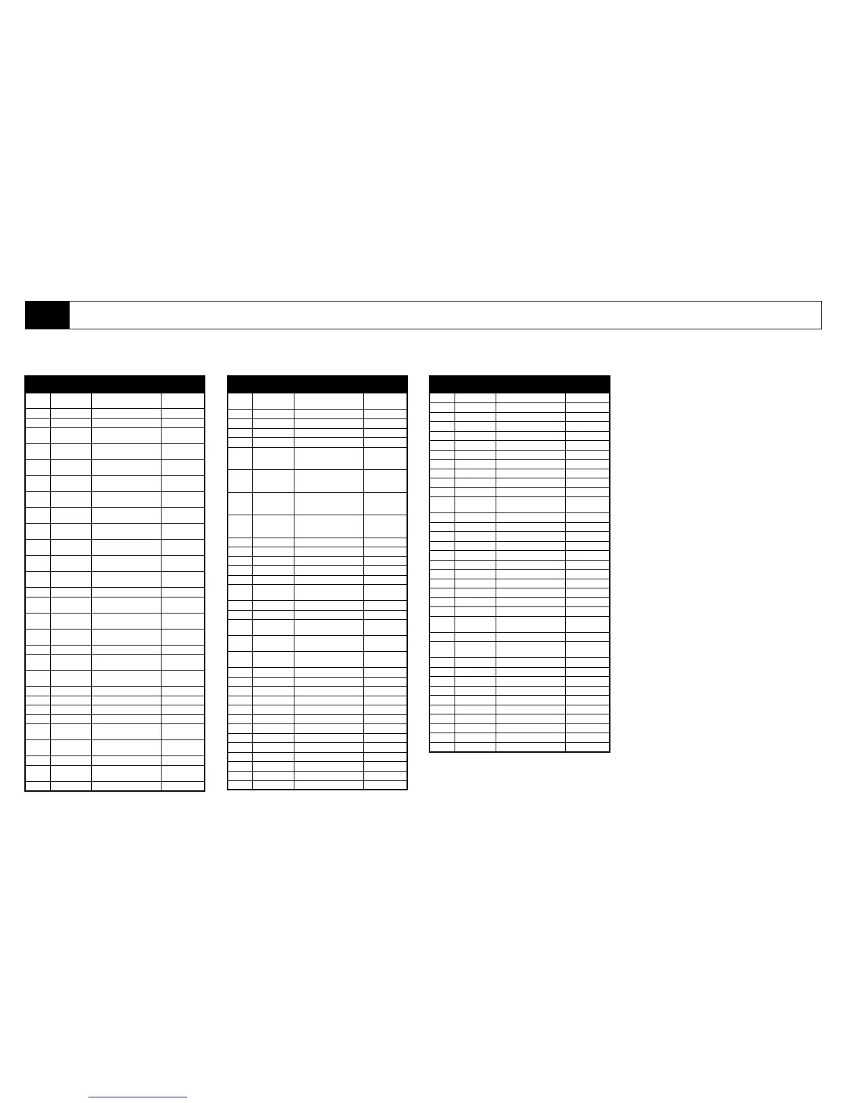
Table 5-3: Hydraulic Schematic Legend (064148-023)
DESIGNA
TION
NAME FUNCTION LOCATION
CV1 Check Valve Allows oil to flow in one
direction only.
Inline to Pumps P1
and P2.
BRK1 Brake Swing Brake Swing Motor
BRK2-3 Brake Left/Right Brake Rear Drive
CB1-2
Counterbalance
Valve
Boom Extend Counterbalance Boom Extend Cyl
CB3
Counterbalance
Valve
Lift Cylinder Counterbalance Lift Cylinder
CB4-5
Counterbalance
Valve
Swing Motor Counterbalance Swing Motor
CB6-7
Counterbalance
Valve
Master Cylinder Counterbalance Master Cylinder
CB8-9
Counterbalance
Valve
Slave Cylinder Counterbalance Slave Cylinder
CB10-11
Counterbalance
Valve
Jib Cylinder Counterbalance Jib Cylinder
CB12-13
Counterbalance
Valve
Axle Extend Cylinder
Counterbalance
Axle Extend Cylinder
CB14
Counterbalance
Valve
Axle Extend Cylinder
Counterbalance
Axle Extend Cylinder
CB15
Counterbalance
Valve
Axle Extend Cylinder
Counterbalance
Axle Extend Cylinder
CB16-17
Counterbalance
Valve
Oscillating Axle Cylinder
Counterbalance
Oscillating Axle
Cylinder (Optional)
CPL Rotary Coupling Provide Fluid Power to Turret Turret
CV1
Check Valve -Aux
Pump
Flow Check - Auxilliary Pump Aux Pump
CV2-3 Check Valve
Flow Check - Hi/Low Torque
Circuit
Torque Valve - V17
CV4
Check Valve - Pilot
Operated
Flow Control - Axle Extend Logic
Axle Extend Logic
Valve
CYL1 Lift Cylinder Raise Boom Turret
CYL2
Upper Extend
Cylinder
Extend Boom Inside Boom
CYL3
Lower Extend
Cylinder
Extend Boom Inside Boom
CYL4 Master Cylinder Level Platform Boom
CYL5 Slave Cylinder Level Platform Boom
CYL6 Jib cylinder Raise Jib Jib
CYL7-8 Steering Cylinders Steer Machine Front Axle
CYL9-10
Axle Extend
Cylinders
Extend/Retract Front Axle Front Axle
CYL11-12
Axle Adjust
Cylinders
Adjust Oscillating Axle (Optional) Front Axle (Opt)
FLC1 Flow Control Valve Control Flow to Boom Functions Main Valve Block
FLO1 Flow Divider
Control Flow to Right Drive
Motors
FLO2 Flow Divider Control Flow to Drive Motors
FLO3 Flow Divider
Control Flow to Left Drive
Motors
FLO4 Flow Divider Control Flow to Platform Rotate
FLT1 Filter Tank Filter Tank
FLT2-3 Filter Suction Strainer Tank
FLT4 Filter Pump Filter Drive Pump
LSCV1
Load Sense
Compensator
Valve
Bypass excess oil from Dump
Circuit
Main Valve Block
LSCV2
Load Sense
Compensator
Valve
Bypass excess oil from Extend
Circuit
Main Valve Block
LSCV3
Load Sense
Compensator
Valve
Bypass excess oil from Lift
Circuit
Main Valve Block
LSCV4
Load Sense
Compensator
Valve
Bypass excess oil from Swing
Circuit
Main Valve Block
MOT1 Motor Swing Motor Turret
MOT2 Drive Motor Left Front Drive Motor Left Front Axle
MOT3 Drive Motor Right Front Drive Motor Right Front Axle
MOT4 Drive Motor Left Rear Drive Motor Left Rear Axle
MOT5 Drive Motor Right Rear Drive Motor Right rear Axle
ORF1-2 Orifice
Flow Control - Axle Extend
Cylinders
Front/Rear Axle
ORF3 Orifice Flow Control - Swing Motor Main Valve Block
ORF4 Orifice Flow Control - Steering Main Valve Block
ORF5 Orifice
Flow Control - Axle Extend Logic
Valve
Axle Extend Logic
Valve
ORF6 Orifice
Flow Control - Left rear Drive
Motor
Left Rear Drive Mtr.
ORF7 Orifice
Flow Control - Right Rear Drive
Motor
Right Rear Drive
Motor
ORF8 Orifice Flow Control - Swing Motor Swing Motor
ORF9 Orifice Load Sense Main Valve Block
PUMP1 Drive Pump Drive Pump Engine Module
PUMP2 Pump Auxilliary Lowering Engne Module
PUMP3 Pump Boom Functions Engine Module
ROT Rotator Cage Rotator Platform
RV1 Relief Valve Dump Circuit Relief Valve Main Valve Block
RV2 Relief Valve Extend Circuit Relief Valve Main Valve Block
RV3 Relief Valve Extend Circuit Relief Valve Main Valve Block
RV4 Relief Valve Lift Circuit Relief Valve Main Valve Block
RV5 Relief Valve Swing Circuit relief Valve Main Valve Block
RV6 Relief Valve Drive Circuit Relief Valve Main Valve Block
RV7 Relief Valve Drive Circuit Relief Valve Main Valve Block
DESIGNA
TION
NAME FUNCTION LOCATION
RV8 Relief Valve Axle Extend Relief Valve Main Valve Block
RV9 Relief Valve Axle Retract Relief Valve Main Valve Block
RV10 Relief Valve Jib Circuit Relief Valve Main Valve Block
RV11 Relief Valve Platform Rotator Relief Valve Main Valve Block
RV12 Relief Valve Platform Rotator Relief Valve Main Valve Block
SW1 Pressure Switch Brake Pressure Switch Left Brake
SW2 Pressure Switch Brake Pressure Switch Right Brake
SV1 Shuttle Valve Axle Extend Shuttle Valve Main Valve Block
SV2 Shuttle Valve Drive Circuit Shuttle Valve Main Valve Block
SV3 Shuttle Valve Logic Circuit Shuttle Valve Main Valve Block
SV4 Shuttle Valve Logic Circuit Shuttle Valve Main Valve Block
SV5 Shuttle Valve
Master Cylinder Circuit Shuttle
Valve
Main Valve Block
SV6-7 Shuttle Valve Logic Circuit Shuttle Valve Main Valve Block
SV8 Shuttle Valve Swing Circuit Shuttle Valve Main Valve Block
SV9 Shuttle Valve Logic Circuit Shuttle Valve Main Valve Block
SV10 Shuttle Valve Lift Circuit Shuttle Valve Main Valve Block
SV11 Shuttle Valve Logic Circuit Shuttle Valve Main Valve Block
SV12 Shuttle Valve Extend Circuit Shuttle Valve Main Valve Block
V1 Dump Valve Dump Circuit Valve Main Valve Block
V2 Extend valve Boom Extend Circuit Valve Main Valve Block
V3 Lift Valve Lift Circuit Valve Main Valve Block
V4 Swing Valve Swing Circuit Valve Main Valve Block
V5 Boom Power Valve Power to Boom Functions Main Valve Block
V6
Master Cylinder
Valve
Master Cylinder Circuit Valve Main Valve Block
V7 Drive Valve Power to Drive Motors Main Valve Block
V8
Axle Extend/
Retract
Extend/Retract Axles Main Valve Block
V9 Jib Valve Raise/Lower Jib Jib Valve Block
V10 Rotator Valve Rotate Platform Jib Valve Block
V11-12 Axle Extend Valves Extend Axles Axle Extend Block
V13 Axle Extend Valve Axle Extend Logic Valve Logic Valve Block
V14 Drive Motor Valve Left Drive Motor Valve
V15 Drive Motor Valve Right Drive Motor Valve
V16 Axle Lock Valve Axle Lock Valve
V17 Torque Valve Torque Valve
V18 Brake Valve Brake Apply Valve
V19 Drive Motor Valve Drive Motor Control Valve Drive Motor
DESIGNA
TION
NAME FUNCTION LOCATION