SB80 Work Platform - European 3-27
M
AINTENANCE
Section
3.19
Test the actuator for proper operation and leakage
prior to securing the endcap with set screws. Mark
the relative position of endcap and housing and
check the marks periodically during the tests below
to ensure that the endcap does not back out. Apply
pressure to the actuator ports and check breakaway.
The breakaway should be about 13,8 bar (200 PSI).
Alternately apply pressure to port on the opposite
side of the piston and check for axial movement. The
axial movement should not exceed ,5 mm (.020”). If
the axial movement is excessive retighten the end
cap. Apply 206,8 bar (3000 PSI) pressure to one port
until piston bottoms out and the actuator rotation
stops. Remove non-pressurized hydraulic line and
check for internal and external leakage. Repeat leak-
age test on opposite actuator port.
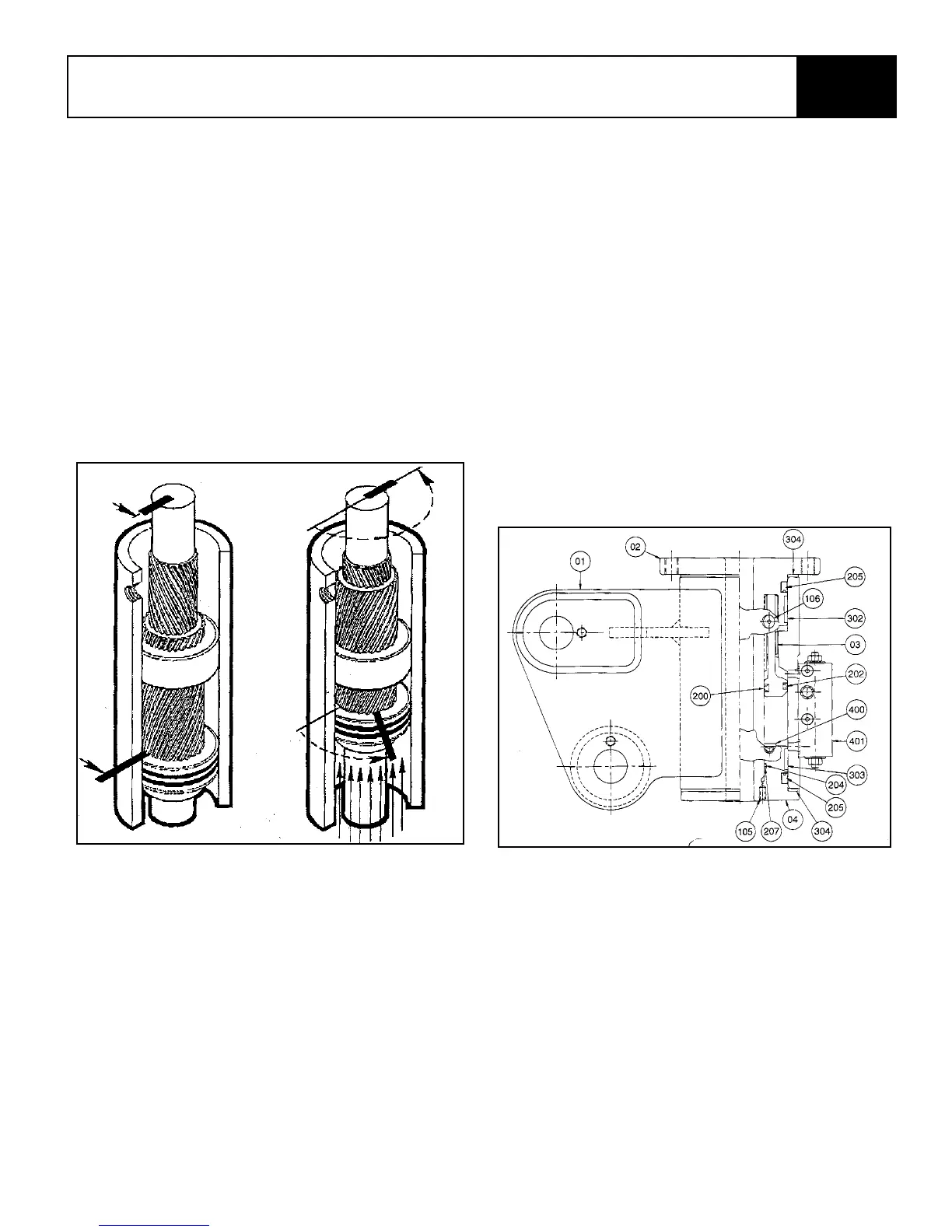
Figure 3-33: Rotary Actuator
Testing and Storage
All HP-9K actuators are tested and operated through
at least twenty-five (25) full cycles at 158,5 bar (2300
PSI) and proof tested at 310,3 bar (4500 PSI) for
structural integrity. Both tests are conducted through
the actuator with the valve installed.
Helac Corporation actuators are normally shipped
filled with petroleum base hydraulic oil. The ports are
plugged with the proper high strength steel plugs to
prevent leakage during shipment.
Hydraulic Line Attachment
The hydraulic lines from the control valve to the actu-
ator should be as short as possible. If the lines hold
more oil than the actuator displaces, the oil is cycled
back and forth, and not allowed to flow to tank for fil-
tering and cooling, resulting in accelerated actuator
wear.
Figure 3-34: Cage Rotator
Install set screws (105) and stake to insure they will
not back out during actuator operation.
Bars indicate starting
positions of piston and
shaft. Arrows indicate
direction they will
rotate. The housing
with integral ring
gear remains
stationary.
As fluid pressure is
applied, the piston is
displaced axially while
the helical gearing
causes the piston and
shaft to rotate simulta-
neously. The double
helix design com-
pounds rotation: shaft
rotation is about twice
that of the piston.