Commissioning vacon • 15
24-hour support +358 (0)201 212 575 • Email: vacon@vacon.com
4
4.2.1 Protocol in use
When value is changed to one, protocol stack is activated.
Please notice that if protocol is stopped (for example protocol is set to zero from panel) and com-
munications have been open, it might be that stack cannot be reinitialized during the next few min-
utes. This is because TCP/IP stack waits for certain time before releasing previously reserved
socket. This happens because TCP/IP stack needs to make sure that all packets sent previously ar-
rive at their destination(s).
4.2.2 Output Instance
Defines which output instance is used (for incoming data to the drive). For details see Chapter 8..
4.2.3 Input Instance
Defines which input instance is used (for outgoing data from the drive). For details see Chapter 8.
4.2.4 Communication timeout
It defines how much time can pass from the last received message from the Master Device before
a fieldbus fault is generated. For EtherNet/IP this value is considered as an additional timeout. The
protocol itself has timeout mechanism (Requested Packet Interval (RPI) multiplied by Connection
Timeout Multiplier (CTM)). When it notices that the connection has been lost, a fault activation is
started. If communication timeout value is zero, the fault is activated immediately, otherwise the
fault activates after a specified time. If the connection is reopened before the specified time has
elapsed, no fault is activated.
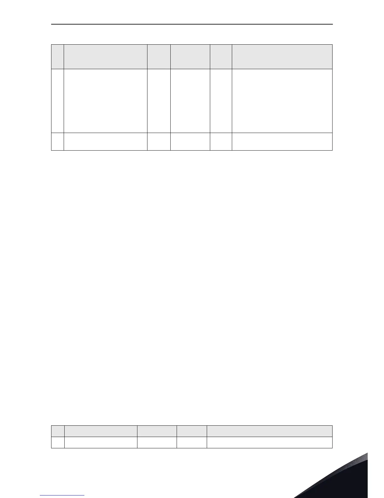
4.3 EtherNet/IP monitoring menu
3
Input Instance 71 "70" (1),
"71" (2),
"73" (3),
"75" (4),
"107" (5),
"117" (6),
"127" (7),
"137" (8)
2419
d
Ethernet/IP input assembly
instance. See Chapter 8.
4
Communication Timeout 10 0…65535 2420
d
Communication timeout in sec-
onds
Table 5. Monitoring Menu
# Name Type / Values ID Definition
1
Reset Counters “Button” 2421
d
Resets monitoring counters.
Table 4. Parameters Menu
# Name Default
Range /
Accepted
Values
ID Definition