8
vacon • 74 Assembly instances implemented by vacon® 100 family
Tel. +358 (0) 201 2121 • Fax +358 (0)201 212 205
Running2 bits depends further on the “Direction Indication” bit 2 of the VACON®
FBFixedStatusWord as follows:
8.4.4 Direction Indication bit in VACON® FBFixedStatusWord
See chapter 8.4.3.
8.4.5 Fault Indication bit in VACON® FBFixedStatusWord
The “Fault Indication” bit 3 in the VACON® FBFixedStatusWord is mapped to the “Faulted” bit in an
Input Assembly which supports this bit.
8.4.6 Alarm Indication bit in VACON® FBFixedStatusWord
The “Alarm Indication” bit 4 in the VACON® FBFixedStatusWord is mapped to the “Warning” bit in
an Input Assembly which supports this bit.
8.4.7 Setpoint Reached Indication bit in VACON® FBFixedStatusWord
The “Setpoint Reached Indication” bit 5 in the VACON® FBFixedStatusWord is mapped to the
“AtReference” bit in an Input Assembly which supports this bit.
8.4.8 Fieldbus Control indication in Input Assemblies
The selected control place is indicated in the Input Assemblies which contain the “CtrlFromNet” bit.
If the control place is assigned to fieldbus then this bit is set to 1, else it is 0.
8.4.9 Fieldbus Reference indication in Input Assemblies
The selected reference is indicated in Input Assemblies which contain the “RefFromNet” bit. If the
reference is assigned to fieldbus then this bit is set to 1, otherwise it is 0.
8.4.10 FBSpeedReference in percentage
This is the reference 1 to the AC drive. The allowed scaling is from 0 to 10000. In the application, the
value is scaled in percentage of the frequency area between set minimum and maximum frequency.
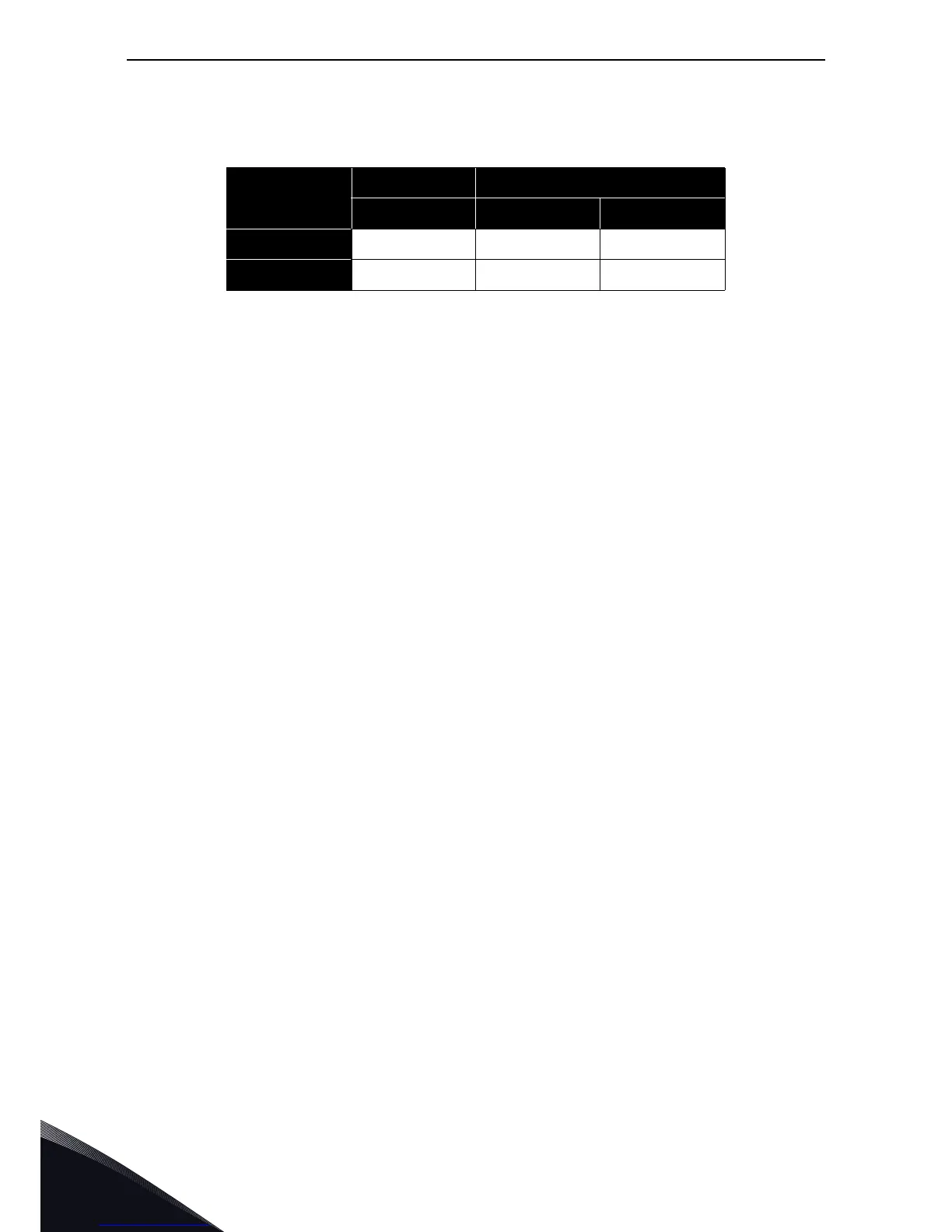
Table 77. Run/Stop Bit Indication Map
Run/Stop = 0 Run/Stop = 1
Direction = X Direction = 0 Direction = 1
Running1 010
Running2 001