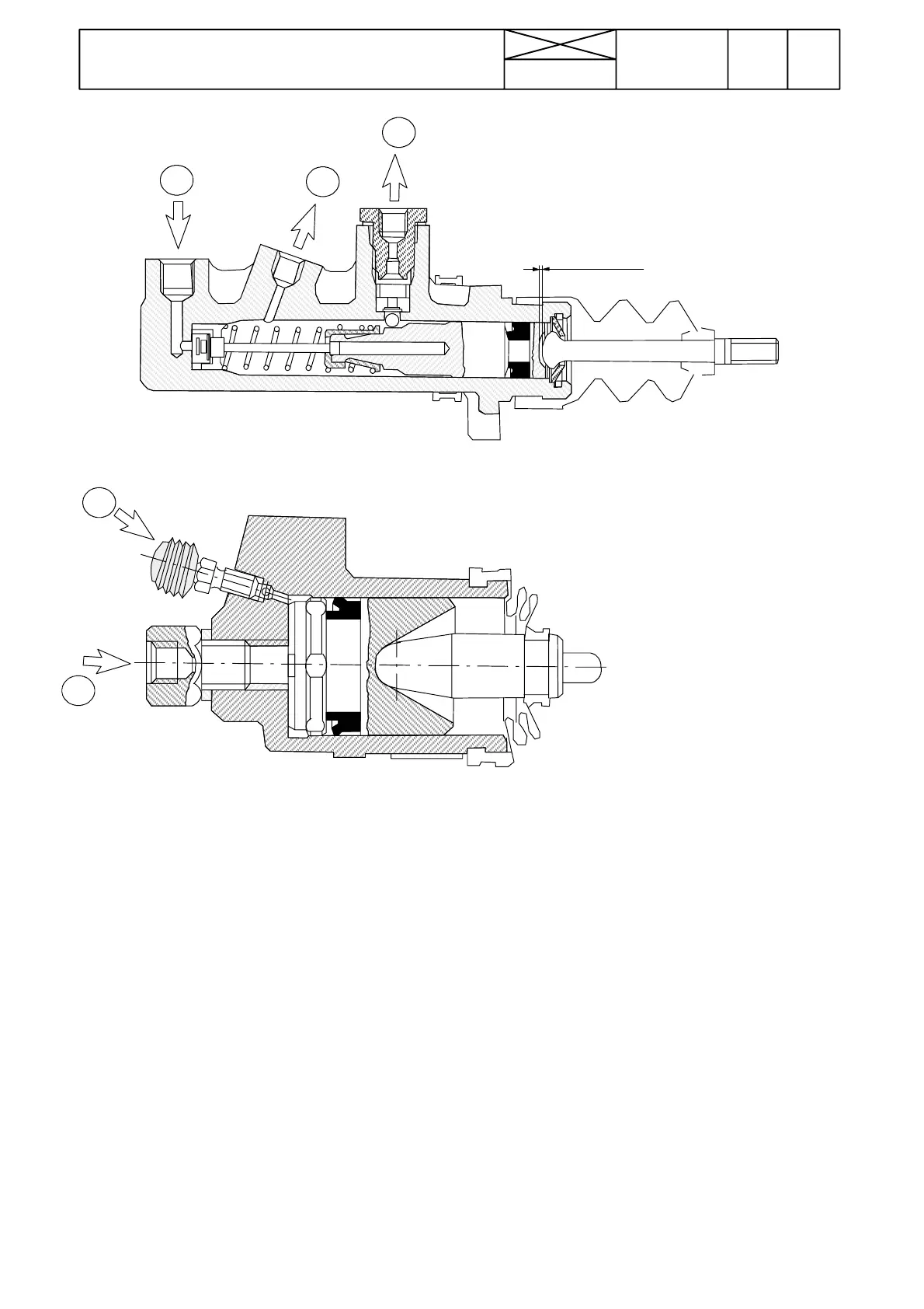
Figure 4. Master cylinder
Figure 5. Brake cylinder
C l e a r a n c e 1 --- 3 m m
880
Models Code Page
51. Brake system
8. 11. 1990
6000--8750 510 4
12
3
4
5
Thebrakefluidflowsfromthereservoirthroughpipe(1)into
the master cylinder. When the pedals are depressed, the
non---return valve at the front end of the master cylindercloses
preventing oil from returning to the reservoir. The fluid, now
under pressure in the cylinder, flows through pipe (2) to hole
(4) at the front end of the brake cylinder behind the piston and
forces out the thrust rod.
Thevalvesandtheintermediatepipe(3)inthemastercylin-
ders serve as an equalising mechanism, if the mechanicalset-
tingof the two brakes differs.When the pedals are depressed,
the pistons actuate the valves so that they open and any pres-
sure differences in the brake circuits are equalised through
theintermediatepipe(3).
If only one of the brakes is applied, the valve is opened by the
piston, thus pressurising the intermediate pipe (3). This
causes the valve in the other (not actuated) master cylinder to
close. Oil under pressure now flows from the master cylinder
which is being applied to the corresponding brake cylinder.
The brake system bleeder nipples (5) are placed on top of the
respective brake cylinders.