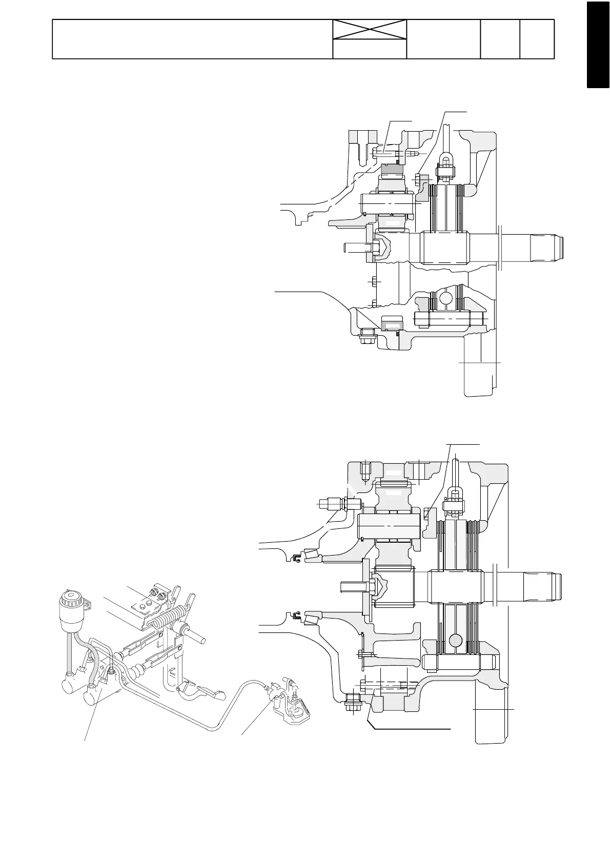
Figure 2. Brake housing with final drives 300
Figure 3. Brake housing with final drives 450 and 650.
The brake master cylinders and the brake fluid reser-
voir are positioned to the right on the cab front wall. The
brake system has two brake cylinder with in---built
equalising valves, which ensure even braking action
when the brake pedals are latched together.
The brake discs are fitted on splines on the inner drive
shaft in the brake housing. The brake system and the
gearbox use the same oil.
The bleeder nipples are positioned on top of the brake
cylinders
During brake application the force from the brake cylin-
ders is transferred, via levers, to the brake discs. The
thrust plates turn in opposite direction and the balls be-
tween the plates force them against the brake discs and
brake action is obtained.
Master cylinder
Brake cylinder
229
Model Code Page
51. Brake system
1. 9. 2002
6000--8950 510 3
8. 11. 1990
Z=63
Z=23
Z=15
70 Nm
80 Nm
Z=82
Z=33
Z=14
125 Nm
80 Nm