Model ATRT-03 (v) Operating Instruction
12
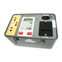
Table 7-1. Model ATRT-03 Front-Panel Controls, Indicators, and Connectors
Fig. 7-1 Index Panel Markings Functional Description
1
EMERGENCY
TURN OFF
“PUSH”
Emergency turn-off test voltage switch.
2
H
H Voltage Test Connector.
3
None (Display)
LCD screen: 4 line by 20 character, back-lighted
and legible in the sunlight. Displays menus, test
results and status readouts.
4
X
X Voltage Test Connector.
5
120/240 Vac, 1A,
50/60Hz
Fuse: 250Vac
2A
Input power connector and fused power switch
with third-wire safety ground.
6
None (Wing nut)
ATRT-03 ground stud. Connect the ground stud
to substation ground.
7
None (Printer)
Thermal printer, 4.5-inch wide.
8
None (Keypad)
Pushbutton operating controls, 16-keys.
9
TEST IN PROGRESS
Red LED, Test In Progress. This LED flashes
when the ATRT-03 responds to a command or
when test voltage is applied to the test
transformer. The ATRT-03 flashes the LED and
beeps at a one second rate during tests.
10
RS-232C
Computer-Interface Port, 9-pin, female DB type
connector. RS-232C interface allows the
ATRT-03 to interface with an IBM PC
computer. Data rate is set to 19,200 baud, 1 start
bit, 8 data bits, 2 stop bits, and no parity bit.
Connector pin functions are:
PIN SIGNAL
2 Rx
3 Tx
5 Gnd