Model ATRT-03 (v) Operating Instruction
64
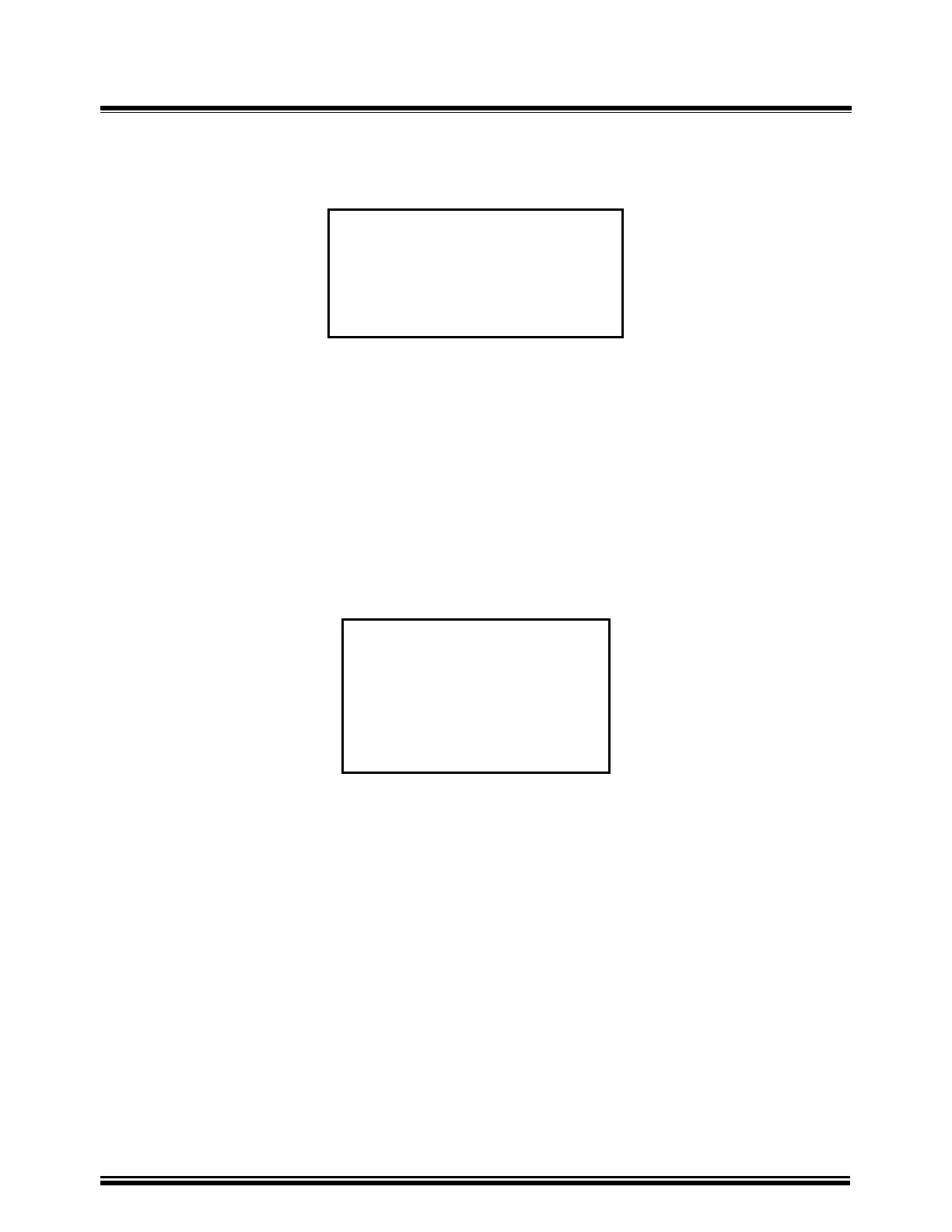
20-3. Printing Test Plan Menu 3
TEST PLAN DIRECTORY
“UP” TO SCROLL FWD
“DWN” TO SCROLL RVS
Figure 20-3. Test Record Menu
a. Description: The user scrolls to the selected test plan stored in memory to print.
b. Origin: From the “Start-Up” menu (see Figure 14-1), press key 2 (SET UP). Press key 4 (NEXT
PAGE). Press key 4 (TEST PLAN). Press key 4 (PRINT TEST PLAN). Press key 2 (SCROLL TO
SELECT).
c. Action Option: Use “∧” or “∨” to test plan. Press “ENTER” key to print test plan.
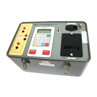
2V SNG PHS TAPS: 5
WESTINGHOUSE
200288
Voltage Reg Test Plan
Figure 20-3A. Typical Test Plan Header
Note:
1. Test number residing in memory is #2.
2. Transformer type is “SINGLE PHASE VOLTAGE REGULATOR”.
3. There are 5 taps identified in this test plan.
4. A “Voltage Regulator” test plan is indicated by letter “V” (after the test plan number).
5. A “Load Tap Changer” test plan is indicated by letter “L” (after the test plan number).
6. Transformer manufacturer is “Westinghouse”
7. Transformer type is “200288”