SmartCabinet2-E Series Computer Room Solution Product User Manual
Chapter 2 Product Installation And Commissioning 9
Dismantle or install floating nut
Remove the foot press M8 bolt
Assist the removal of packaging, installation of ECO fan module
Detect power distribution system status and cable wiring
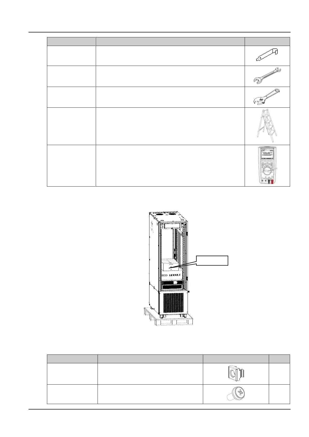
The accessories are placed in the accessory box inside the cabinet. As shown in Figure 2-1, open the accessory box
to obtain the accessories. The list of accessories is as follows:
Figure 2-1 The accessories
Table 2-3 The accessories list
Used with M6 screws for the installation of user parts
in the cabinet
Used for the installation of user parts in the cabinet