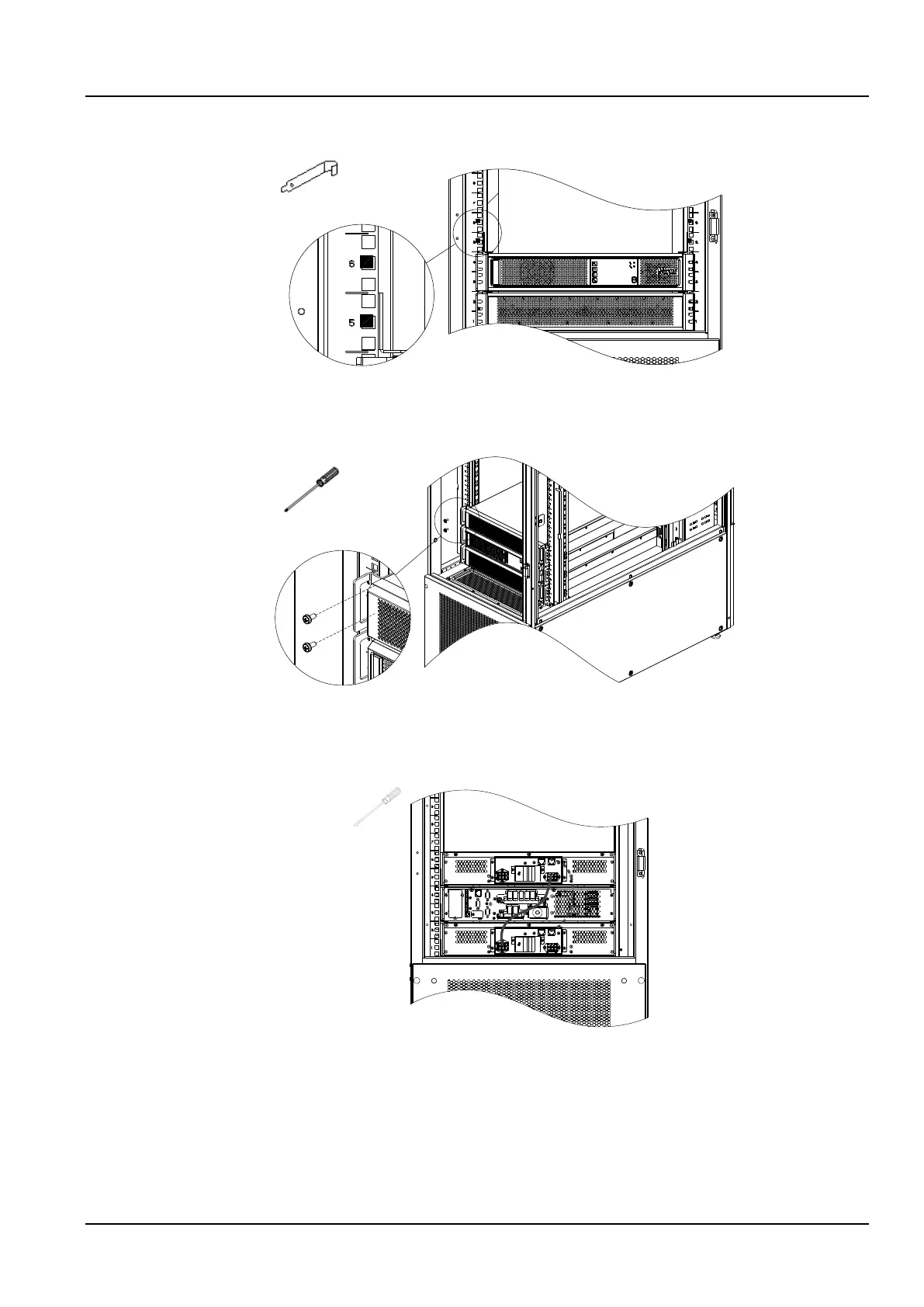
5) Install floating nuts (4 pcs) at the 5U and 6U intermediate holes of the left and right columns, as shown in
Figure 2-20.
Figure 2-20 Install the floating nuts 2
6) Place the battery pack on the guide rail, install it on the 5th and 6th U positions on the column, and fix it with
M6×16 screws (4 pcs), as shown in Figure 2-21.
Figure 2-21 Fixing the battery pack
7) Use the battery module's own power cable and communication cable to connect the battery according to
Figure 2-22. The solid line in the figure is the power cable, and the dotted line is the communication cable. After
connecting, use a flat-blade screwdriver to tighten the power cable loosened screw.
Figure 2-22 Battery wires connection
2.2.6 GSM MODEM installation (optional)
1. Take out the GSM MODEM from the cabinet accessory bag.
2. Install the SIM card and GSM MODEM antenna according to Figure 2-23.