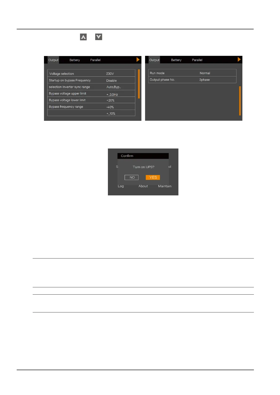
2) Press the arrow keys or to select and set the relevant parameters (take “output” as an example), See
the Figure 2-33. At the same time, configure the battery type in the Battery option according to the selected battery
type.
Figure 2-32 Output Interface
5. Press the ON button on the UPS panel for 2 seconds, and the LCD pops up a dialog box as shown in the Figure 2-
34. When the user clicks “Yes”, the running indicator (green light) flashes, the inverter starts up, and the running
indicator lights up.
Figure 2-33 UPS turn-on Dialog
6. Measure if the inverter output voltage is normal. If the battery is not connected, the fault indicator flashes; if the
battery is connected, the fault indicator is off.
7. Close the UPS output MCB.
8. Close the air conditioner MCB and wait for the air conditioner to start.
9. Close the PDU MCB to confirm that the PDU display panel data is normal. Whether the port indicators are
illuminated in sequence.
10. Close the 12V and 24V DC output and wait for the LCD communication to be normal. Log in to the
SmartCabinet2-E system and confirm that the parameters are displayed normally.
Notices
1. The PMU contains an SPD module. When the SmartCabinet2-E system is powered on, ensure that the SPD on the PMU works
normally, confirm that the front sighting port of SPD is green.
2. Before the SmartCabinet2-E system starts up, make sure that the maintenance bypass switch is disconnected and locked by the
sheet metal lock.
Warning
The SmartCabinet2-E system must be started up by trained and authorized professional technicians. It is recommended to be
performed by the staff of Vertiv Tech Co., Ltd. Customer Service Center.
2.3.5 System commissioning
1. After startup, the default display interface is displayed via the LCD.
2. Through the LCD local display, click "Settings" -> "Configuration" to display configuration selection interface, select
the appropriate configuration options according to the device connection, as shown in the Figure.2-35.