2.2.8 User Cable Connection
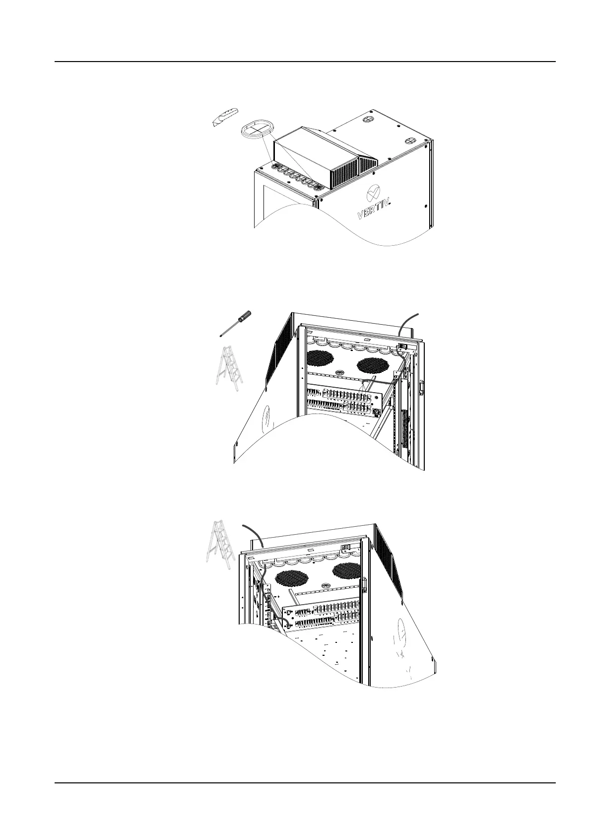
1) Use a utility knife to cut open the two guard rings on the left and right of Figure 2-27;
Figure 2-26 Open the guard rings
2) The power cable is connected to the cabinet through the right guard ring, and the length of the connected cable is
about 0.6m. Connect the cables to the general input “L”, “N” and “PE” of the PMU terminal block shown in the figure
below.
Figure 2-27 Power wires connection
3) Connect the communication cable through the left guard ring to the cabinet. The length of the connected cable is
about 0.6m. Connect to the “LAN1” port at the end of the PMU.
Figure 2-28 Communication wires connection
2.2.9 Installation Inspection
Check the installation against the installation checklist, and do not connect to the power and test the unit until the
inspection is passed.