EasyManua.ls Logo

Vertiv Tech SmartCabinet2-E Series - Installation Environment

Default Icon
87 pages
Print Icon
To Next Page IconTo Next Page
To Previous Page IconTo Previous Page
Loading...
SmartCabinet2-E Series Computer Room Solution Product User Manual
10 Chapter 2 Product Installation And Commissioning
Name
Purpose
Appearance
Quantity
295mm black cable-ties
Binding wires
70
100mm black cable-ties
Binding wires
30
Cable tie base
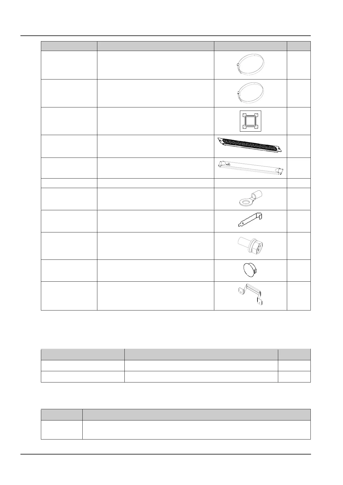
Used for fixing the cable
10
1U dummy panel with
brush
Used for blocking the U position with cable passing
1
1U plastic blind plate
Used for blocking U position
12
UPS User Manual
/
1
OT terminal
Clamped onto the user input power cable
4
Floating nut handle
Remove or install the floating nut
1
Combination screw
M5*12
Used for the installation of user parts in the cabinet
6
Plastic Parts
plug a hole on cabinet
4
AC handle
Dismantling and installing AC
1
2.1.3 Installation Environment
Cabinet information
Table 2-4 Cabinet information
Cabinet status
Dimensions (width × depth × height)
Weight
Wooden packaging
770mm×1420mm×2260mm
450kg
Bare cabinet
600mm×1200mm×2000mm
390kg
Installation Environment
Table 2-5 Installation Environment
Item
Requirements
Site
Ground flatness tolerance 3mm/2000mm
Site height ≥ 2.4m(If the Airduct is including, Site height ≥ 2.7m)

Table of Contents