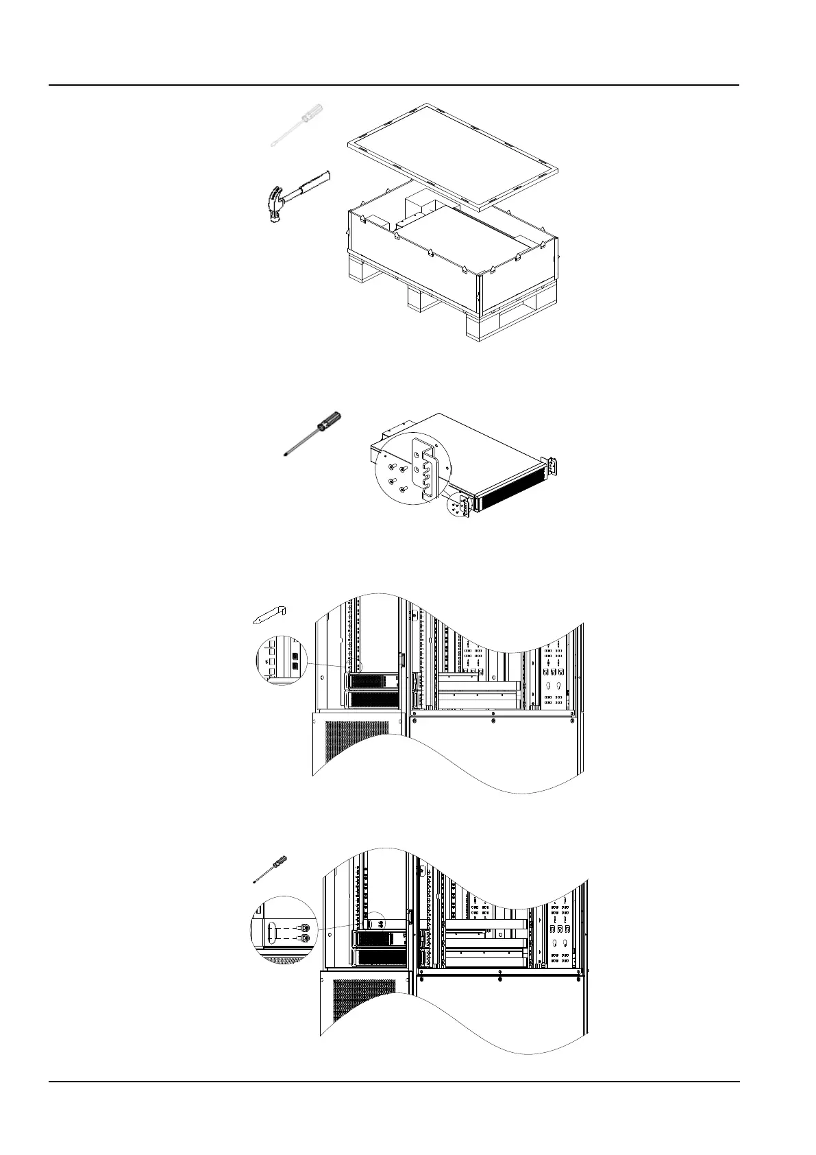
Figure 2-16 Remove the battery package
2) Fix the two mounting ears on both sides of the front panel of the battery pack with M4×10 screws (8pcs), as shown
in Figure 2-17.
Figure 2-17 Install the mounting ears
3) Remove the two side panels of the cabinet and install floating nuts (8pcs) on the two square holes corresponding
to the No.5U position on the column, as shown in Figure 2-18.
Figure 2-18 Install the floating nuts 1
4) Install the rails, fixe with M6×16 screws (8pcs), as shown in Figure 2-19.
Figure 2-19 Install the rails