Figure 2-11 Removal the fan package
Figure 2-12 Install ECO fan module
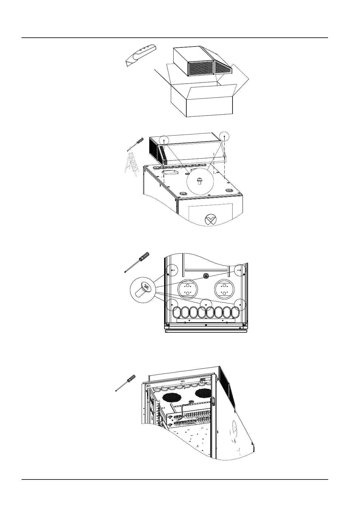
2) Install the 5 PCs of M4x10 screws in the cabinet to fix the ECO fan module, as shown in Figure 2-13.
Figure 2-13 Fixing ECO fan module
3) Connect the fan cable to the “+”, “-”, and “SS” Pins in the “FAN” area of the PMU rear terminal block according to
Figure 2-14 and bind the cable along the way.
Figure 2-14 ECO module wires connection