REV : 6
REV DATE : 1/17
DPN002810
Page :1 /5
Form No.: DPN001040_REV4
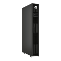
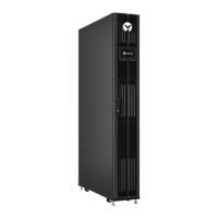
LIEBERT CRV
ELECTRICAL FIELD CONNECTIONS DESCRIPTIONS
300mm (12in.) MODELS
STANDARD ELECTRICAL CONNECTIONS (See unit views for item callouts)
1) High voltage connection through the rear of the disconnect switch box – 1-1/8” (28.6mm) & 1-
concentric knockout.
2) High voltage connection through the top of the unit – 1-1/4” (32mm) & 1-3/4” (44mm) diameter concentric knockout.
3) Electrical service (hard wired) – Refer to serial tag information for unit electrical service requirement.
Three phase – 208/230V 60Hz
Three phase with Neutral – 460V 60Hz Wye (5 wire: 3 phase + neutral + ground).
Single phase – 208/230V 60Hz (Chilled Water only).
Connect to terminals on disconnect switch. Electrical service not by Liebert. Use copper conductors only, Wire p
Refer to specification sheet for total unit full load amps, wire size amps and max over current protective device size.
4) Electrical service (cord connected) – Refer to serial tag information for unit electrical service requirement.
Single phase – 120V 60Hz (Chilled Water only). 1-
3/4” (44mm) diameter knockout provided in the top and bottom of the unit for the
power cord to exit the unit. The power cord is Liebert supplied with a L5-20 plug.
5) Factory installed locking Disconnect Switch
6) Earth ground - Terminal for field supplied earth grounding wire.
7) Low voltage connection through the bottom of the unit - Quantity (2) 7/8” (22mm) diameter knockouts, not shown.
8) Low voltage connection through the top of the unit - Quantity (2) 7/8” (22mm) diameter knockouts.
9) Remote unit shutdown -
Replace existing jumper between terminals 37 & 38 with field supplied normally closed switch having a
minimum 75VA, 24VAC rating. Use field supplied Class 1 wiring.
10) Customer alarm inputs - Terminals for field supplied,
normally closed contacts, having a minimum 75VA, 24VAC rating, between
terminals 3 & 50, 2 & 51, 5 & 55, or 3 & 56. Use field supplied Class 1 wiring. Terminals 5 & 55 not available when optional
Condensate Pump is installed.
11) Common alarm - On any alarm, n
ormally open dry contact is closed across terminals 75 & 76 for remote indication. 1 AMP, 24VAC
max load. Use Class 1 field supplied wiring.
12) Heat rejection interlock - On any call for compressor operation, normally open dry contact is closed across termina
heat rejection equipment. 1 AMP, 24VAC max load. Use Class 1 field supplied wiring.
CANbus ELECTRICAL CONNECTIONS
13) CANbus connector – Terminal block with terminals 49-1 (CAN-H) and 49-3 (CAN-
L) + SH (shield connection). The terminals are
used to connect the CANbus communication cable (provided by others) from the indoor unit to the Liebert MC Condenser.
14) CANbus cable – CANbus cable provided by others to connect to the outdoor condenser. No special considerations are required
when the total external cable connection between the indoor unit and outdoor unit(s) is less than 450FT (137M). For total external
cable connections greater than 450FT (137M) but less than 800FT (243M) a CANbus isolator is required. Contact the Factory.
Cable must have the following specifications:
- Braided shield or foil shield with drain wire
- Shield must be wired to ground at indoor unit
- 22-18AWG stranded tinned copper
- Twisted pair (minimum 4 twists per foot)
- Low Capacitance (15pF/FT or less)
- Must be rated to meet local codes and conditions
- EXAMPLES BELDEN 89207 (PLENUM RATED), OR ALPHA WIRE 6454 CATEGORY 5, 5E, OR HIGHER
15) Do not run in same conduit, raceway, or chase as high voltage wiring.
16) For CANbus network lengths greater than 450FT (137M) call Factory.
SAFETY INSTRUCTIONS: READ ALL SAFETY MESSAGES IN USER MANUAL
BEFORE STARTING ELECTRICAL CONNECTIONS
 Loading...