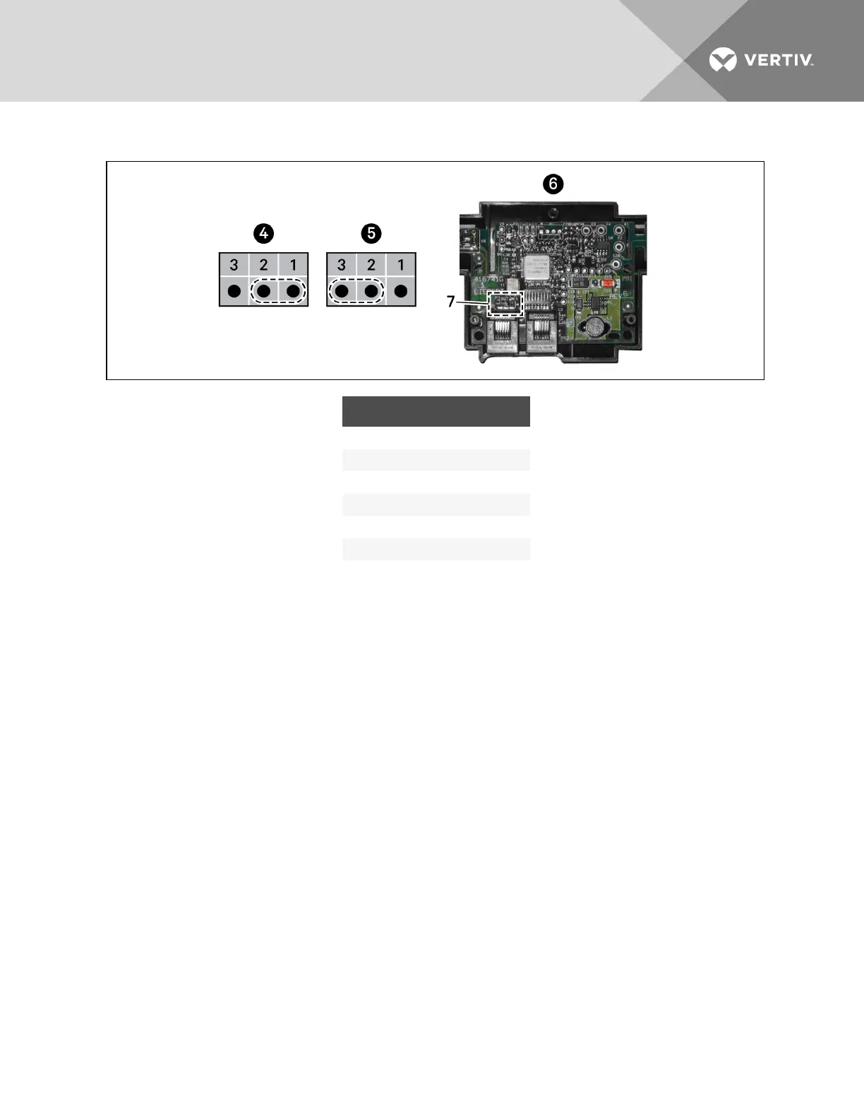
Figure 9.5 Termination-jumper on 2T circuit board
ITEM DESCRIPTION
1 Jumper position
2 Jumper position
3 Jumper position
4 Unterminated
5 Terminated
6 Rear of sensor, cover removed
7 Termination jumper
9.1.3 Routing CANbus cable and preparing for sensor installation
Depending on the CRV model number, the CANbus cables may enter the cooling unit from differing
locations to connect to the return-air temperature sensor.
• For 300-mm (24-in.): CR019 and CR032 models, the CANbus cable may enter through the top
or bottom. See Preparing for sensor-cabling of CRV300-mm(12-in.) units—CR019 and CR032
on the next page.
• For 600-mm (12-in.): CR020, CR035, and CR040 models, the CANbus cable enters through the
top of the unit. See Preparing for sensor cabling of CRV600-mm(24-in.) units—CR020, CR035
and CR040 on page98.
NOTE: Connecting the CANbus sensors requires entering the high-voltage electrical compartment in
the unit. Consider hiring a certified electrician.
Vertiv | Liebert CRV Installer/User Guide | 95