7.3 Electrical Field-connection Descriptions
The electrical connections are described in the submittal documents included in the Submittal Drawings
on page156.
The following tables list the relevant documents by number and title.
DOCUMENT NUMBER TITLE
600-mm (24-in.) Models
DPN001884 Electrical Field Connections Descriptions, 600mm (24in.) Models
DPN002841 CANbus & Interlock Connections between 600mm (24in.) Unit & Liebert MCCondenser
300-mm (12-in.) Models
DPN002810 Electrical Field Connections Descriptions, 300mm (12in.) Models
DPN003036 CANbus & Interlock Connections between 300mm (12in.) Unit & Liebert MCCondenser
DPN003588 Low Voltage Field Wiring Routing, 300mm (12in.) All Models
DPN003589 Power Cable Routing Bottom Entry, 300mm (12in.) Air Cooled & Water Glycol Cooled Models
DPN003590 Power Cable Routing Bottom Entry 300mm (12in.) Chilled Water Models
Table 7.1 Electrical Field-connection Drawings
7.3.1 Locating the Serial Tag andRemovingtheElectricalPanelon600-mm (24-in.)Units
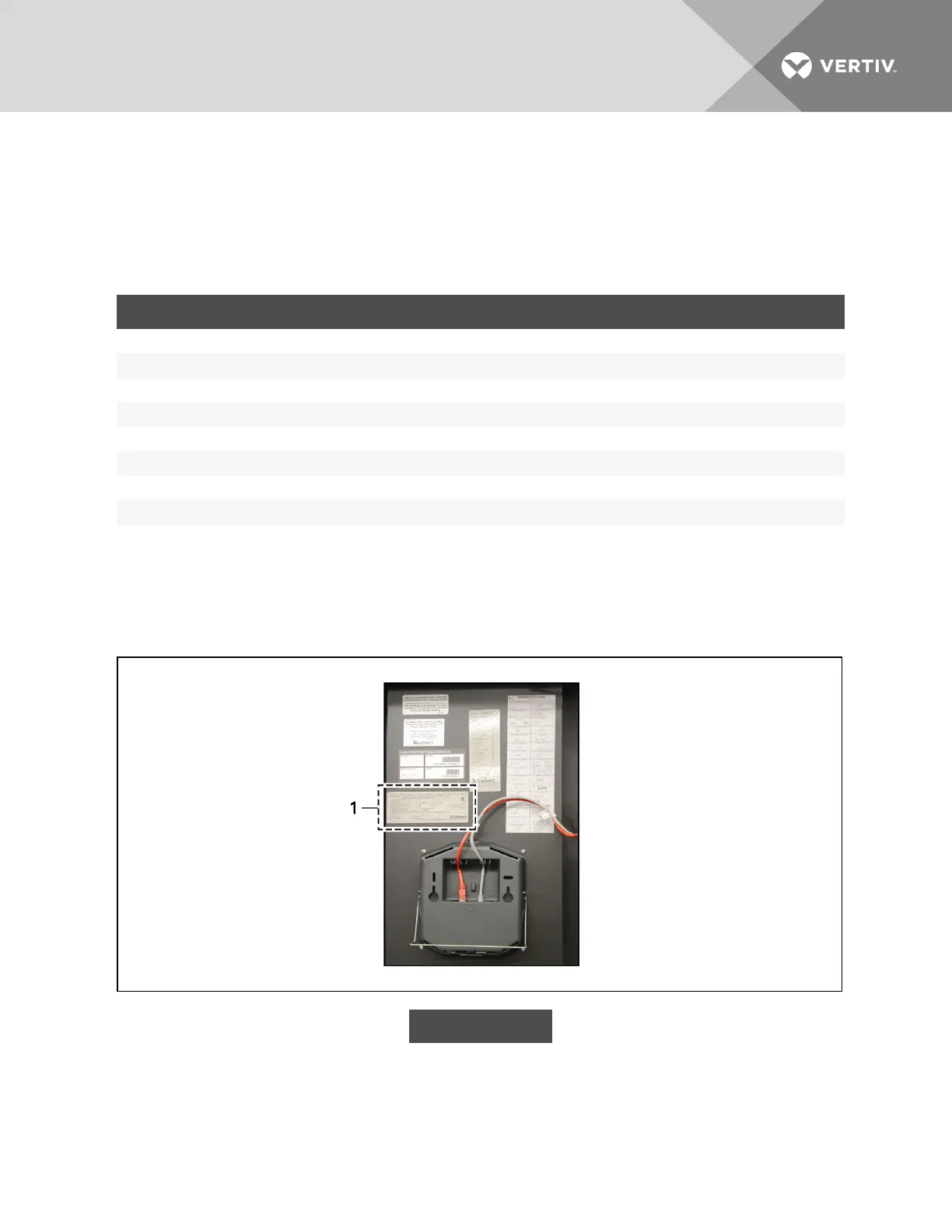
This serial tag on the 600-mm (24-in.) unit is inside the display panel as shown in Figure 7.1 below.
Figure 7.1 Serial tag location—600 mm (24 in.)
ITEM DESCRIPTION
1 Serial tag
To access the electrical panels:
Refer to Figure 7.2 on the facing page, and remove the bolts indicated.
Vertiv | Liebert CRV Installer/User Guide | 74