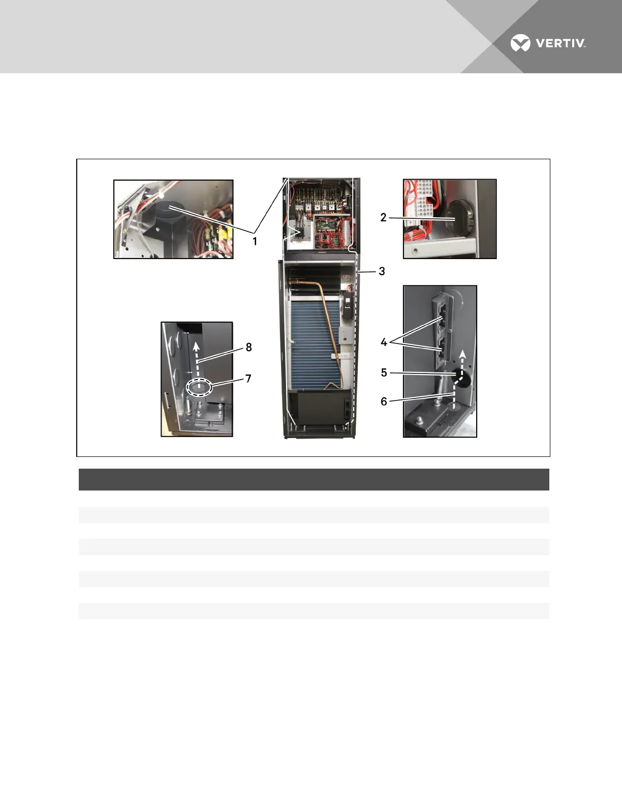
7.3.2 Cable-entry Points on 600-mm (24-in.) Units
Figure 7.3 below shows the high- and low-voltage cable-entry points.
Figure 7.3 Power and control cable entry points and routing—600 mm (24 in.)
ITEM DESCRIPTION
1 High-voltage top-entry point
2 Low-voltage channel opening in side panel
3 Low-voltage cables route from top entry, through the channel opening in the side panel, and connect bottom of the unit to the electrical panel.
4 IntelliSlot bays
5 Low-voltage bottom port entry
6 Low-voltage cable path to electrical panel
7 High-voltage bottom-entry knockout
8 High-voltage cable path
Vertiv | Liebert CRV Installer/User Guide | 76