6.3.2 Chilled-water Loop Piping
For the top connection locations the, refer to the appropriate submittal documents included in the
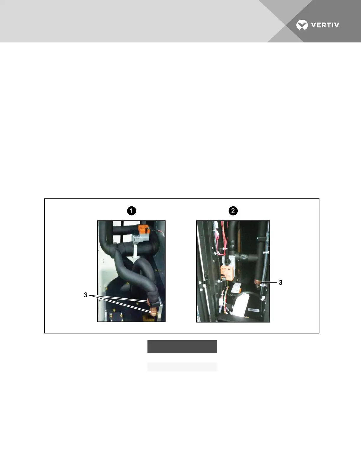
Submittal Drawings on page156. Figure 6.6 below shows the bottom connection locations for the chilled-
water units. Figure 6.7 on the facing page diagrams the chilled-water circuit.
• Use copper tubing or steel pipe.
NOTE: A dielectric fitting is required when using steel pipe.
• Place the tubing on supporting saddles.
• Insulate both tubes.
• Install shut-off ball valves on the inlet and outlet pipes to ease maintenance.
• Install optional thermostats and pressure gauges on the inlet and outlet pipes.
• Install a water drain tap at the lowest point in the circuit.
• Fill the circuit with water or glycol.
• Locate air vents at tops of all risers and any intermediate system high points.
Figure 6.6 Bottom connections on chilled water units
ITEM DESCRIPTION
1 600mm (24 in.) unit
2 300mm (12in.) unit
3 Chilled-water connections
Vertiv | Liebert CRV Installer/User Guide | 56