9.1.2 Terminating the last sensor on the CANbus link
The 2T sensor need not be installed in the numeric-order of their address/sensor number (although it
may be easier for later maintenance). However, the last sensor in the chain must be terminated. All others
must remain un-terminated. We also recommend that you make a record of the sensor numbers along
with the name/number of the rack on which they are installed. Figure 9.4 below shows an example
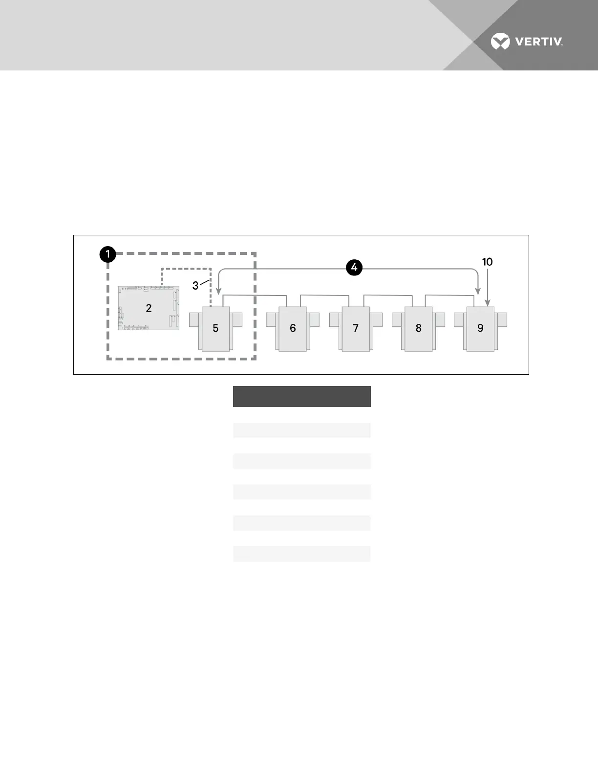
CANbus arrangement.
NOTE: To add sensors, un-terminate final sensor, add sensors to the chain, and terminate the new final
sensor.
Figure 9.4 Sensor CANbus arrangement
ITEM DESCRIPTION
1 Inside the CRV unit
2 iCOM control board
3 Factory wiring
4 CANbus communication link
5 Unit temperature/humidity sensor
6 2T sensor
7 2T sensor
8 2T sensor
9 2T sensor
10 Terminated sensor
To terminate the last sensor:
1. Locate the sensor that will be last on the network.
NOTE: The last sensor on the network will be the sensor with only 1 CAN cable after all sensors are
connected to the CANbus network. See Connecting the CANbus cable and ground on page103.
2. Open the sensor’s case by removing the Phillips-head screws (typically 3) one the rear of the
housing to access the jumper used for terminating.
3. Remove the black jumper from pins 1 and 2, and install it on pins 2 and 3 as shown in Figure 9.5
on the facing page.
4. Replace the sensor cover.
The 2T sensor is terminated in the CANbus link.
Vertiv | Liebert CRV Installer/User Guide | 94