3. Referring to 9.1.1 on page91 and using the non-conductive tool, set the DIP switches for each
sensor to its number in the chain (from sticker applied in step 1).
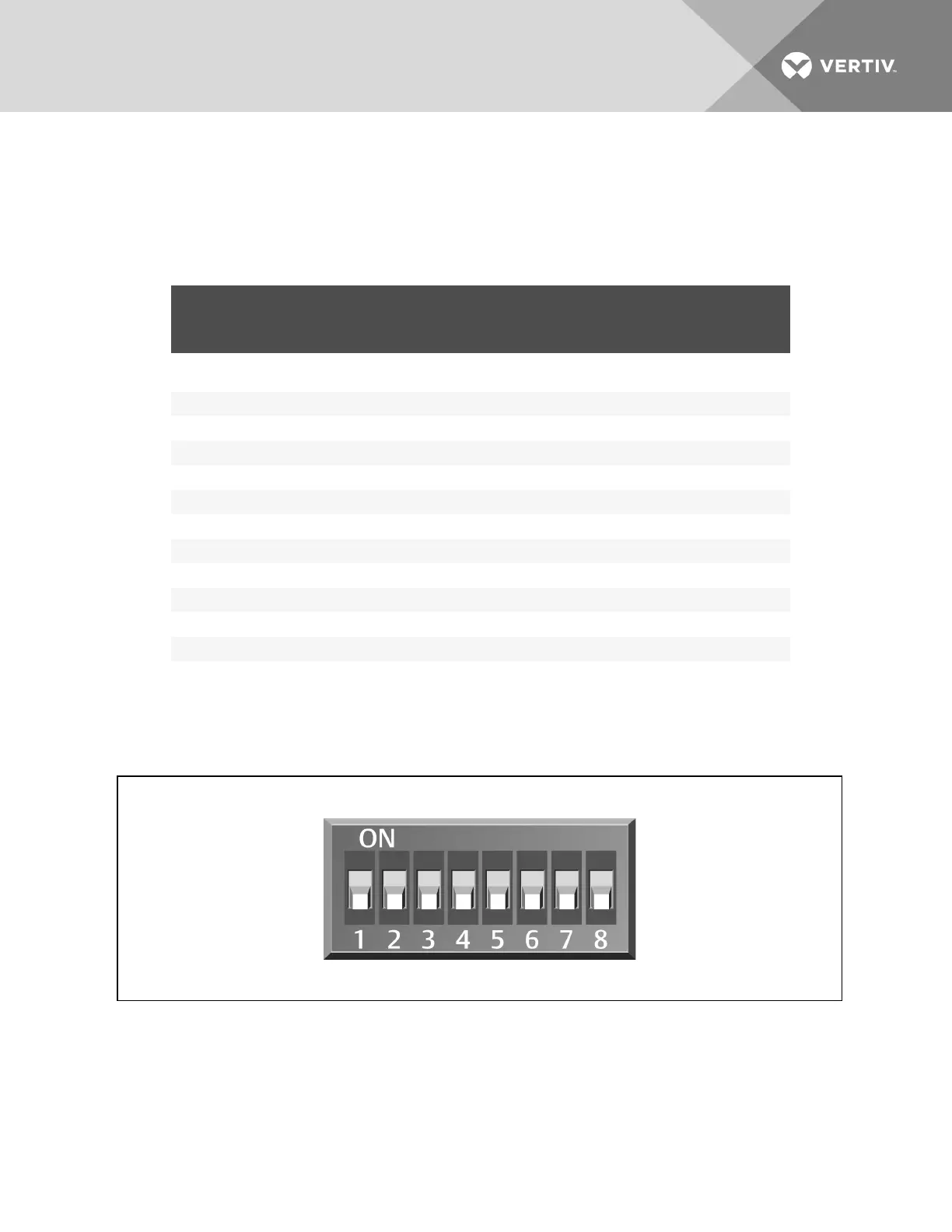
Figure 9.3 below shows a representation of the DIP switches.
4. Confirm that the DIP switches are set correctly for each sensor, and replace the housing cover
if necessary.
2T SENSOR
NUMBER/ADDRESS
DIP-SWITCH POSITION
FACTORY
SETTING
1 2 3 4 5 6 7 8
Factory-supplied
sensors
1 Off Off On Off On Off Off Off Unterminated
2 On Off On Off On Off Off Off Unterminated
3 Off On On Off On Off Off Off Terminated
Optional added sensors
4 On On On Off On Off Off Off Unterminated
5 Off Off Off On On Off Off Off Unterminated
6 On Off Off On On Off Off Off Unterminated
7 Off On Off On On Off Off Off Unterminated
8 On On Off On On Off Off Off Unterminated
9 Off Off On On On Off Off Off Unterminated
10 On Off On On On Off Off Off Unterminated
The last 2T sensor in the array must be terminated. If more than the 3 factory-supplied sensors are installed,
sensor #3 must be unterminated and the last sensor must be terminated.
Table 9.2 DIP-switch settings for wired-remote sensors
NOTE: Up is on, down is off on the DIP switch.
Figure 9.3 DIP switches in 2T sensor
Vertiv | Liebert CRV Installer/User Guide | 93