Each sensor requires a unique address on the CANbus cable connected to the cooling unit. Although not
required, we recommend that you set the DIP-switch sensor-number setting to correspond to the sensor’s
location on the CANbus run. If settings are incorrect, the control will not operate properly.
The DIP switches in 2T sensors included with each Liebert CRV are factory-set according to Table 9.1
below. If adding additional 2T sensors, use the steps that follow to set the DIP switches.
2T SENSOR
NUMBER/ADDRESS
DIP-SWITCH POSITION
FACTORY
TERMINATION
SETTING
1 2 3 4 5 6 7 8
1 Off Off On Off On Off Off Off Unterminated
2 On Off On Off On Off Off Off Unterminated
3 Off On On Off On Off Off Off Terminated
Table 9.1 DIP-switch settings for factory-supplied rack sensors
NOTE: Sensors are connected in a daisy chain to the cooling-unit control board. You can extend the
sensor network (up to 10) by adding sensors to the end of the chain and adjusting the termination
settings. Do not run individual wires from the sensors to the cooling unit.
1. Apply numbered stickers to the sensor housing that corresponds to the sensor’s position in the
chain.
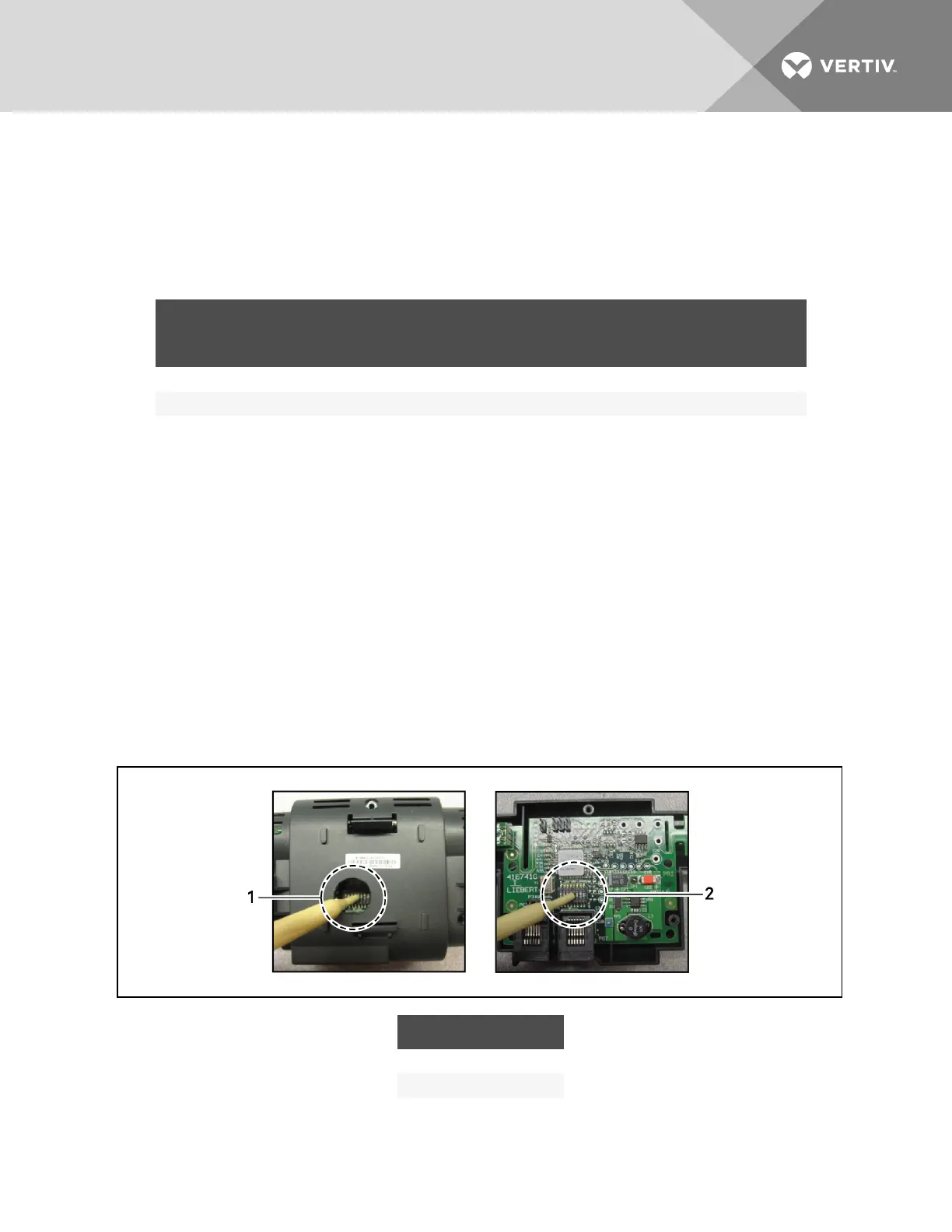
2. Locate the DIP-switch hole on the rear of the sensor housing, Figure 9.2 below.
– or –
If the hole is not present, or the settings are difficult to make through the hole, remove the
cover, Figure 9.2 below, by removing the Phillips-head screws (typically 3).
NOTE: Use the non-conductive DIP-switch tool (included) or a similar tool to set switches.
Do not insert any metal object into the sensor case.
Figure 9.2 DIP-switch opening/DIP switches inside of 2T sensor
ITEM DESCRIPTION
1 Hole in sensor housing
2 Cover removed
Vertiv | Liebert CRV Installer/User Guide | 92