To connect 600mm (24in.) units:
• On each unit, connect one plug on the CAT5 cable to ETH-2 on the rear of the display, and the
other to the network switch, Figure 9.14 below.
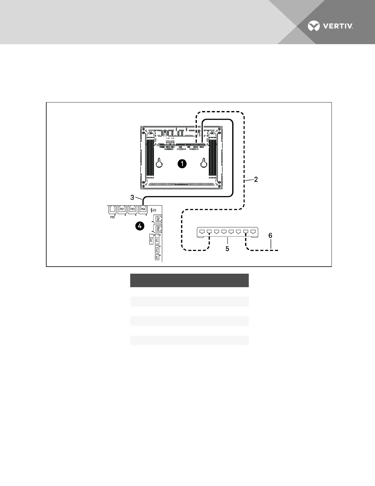
Figure 9.14 Connecting 600mm (24in.) units
ITEM DESCRIPTION
1 Touchscreen (rear view)
2 Ethernet cable (field-supplied)
3 Ethernet cable
4 iCOM I/O board
5 Network switch (field-supplied)
6 to ETH-2 on rear of other cooling-unit touchscreens
9.2.5 Wiring Cooling Units with Wall-mount Displays
NOTE: Cooling units are factory-wired for stand-alone operation. Do not connect the U2U network
cabling before setting the U2U network configuration/groups. Network communication conflicts and
unreliable display readings will result.
NOTE: Before you begin, refer to Preparing for U2U Group Set-up, andConfiguring U2U Network
Settings, in the “Liebert® iCOM™ User Manual,” included with your system documentation.
Large, wall-mount displays may be used to remotely configure, control and monitor all cooling units
connected on the U2U network.
• Each display requires 120VAC or 230VAC input power.
• An AC-adapter wall plug is factory-supplied.
Vertiv | Liebert CRV Installer/User Guide | 108
 Loading...