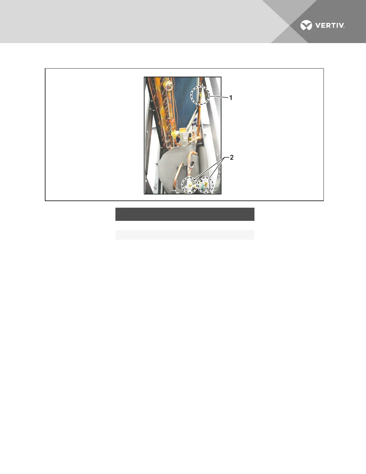
Figure 6.4 Connections for vacuum creation and refrigerant charge—Air-cooled, 300 mm (12 in.)
ITEM DESCRIPTION
1 Service discharge connections for vacuum charging
2 Service suction and discharge connections for vacuum charging
6.2.5 Evacuation, Leak-testing, and Charging Air-cooled Systems without Receivers
A discharge line and liquid line must be field-installed between the indoor unit and the outdoor
condenser. See the appropriate piping schematic, listed in Table 6.1 on page33.
Evacuation and Leak-testing Air-cooled SystemswithoutLiebertLee-Temp™
For proper leak-check and evacuation, you must open all system valves and account for all check valves.
NOTE: The system includes a factory-installed check valve and an additional downstream Schrader
valve with core in the compressor discharge line. Proper evacuation of the condenser side of the
compressor can be accomplished only using the downstream Schrader valve. See the appropriate
piping schematic for your system in the submittal-drawings appendix.
1. If unit power is available, open the unit liquid-line solenoid valves using the evacuation function
for System #1 in the diagnostic section of the Liebert iCOM® control.
– or –
If unit power is not available, connect a field-supplied 24-VAC/75-VA power source directly to
the unit solenoid valve.
2. Connect refrigerant gauges to the suction rotalock valves and discharge-line Schrader valves.
3. Open the service valves and place a 150 PSIG (1034kPa) of dry nitrogen with a tracer of
refrigerant. Check system for leaks with a suitable leak detector.
Vertiv | Liebert CRV Installer/User Guide | 43