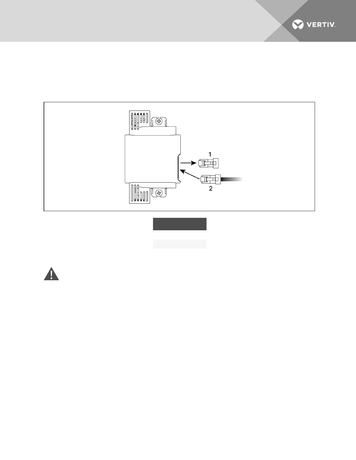
6. Remove the termination plug from the temperature sensor (which is installed on the IntelliSlot
bracket), and discard the plug, and connect the cable to the open CANbus port, Figure 9.7
below.
7. Connect the CANbus ground to the factory-supplied ground connector.
Figure 9.7 Remove Termination plug and insert CAN cable
ITEM DESCRIPTION
1 Termination plug
2 CANcable
Preparing for sensor cabling of CRV600-mm(24-in.) units—CR020, CR035 and CR040
WARNING! Risk of electric shock. Can cause equipment damage, injury or death. Open all local
and remote electric power supply disconnect switches and verify with a voltmeter that power is
off before working within any electric connection enclosures. Service and maintenance work
must be performed only by properly trained and qualified personnel and in accordance with
applicable regulations and manufacturers’ specifications. Opening or removing the covers to
any equipment may expose personnel to lethal voltages within the unit even when it is
apparently not operating and the input wiring is disconnected from the electrical source.
1. Verify that all power entering the unit is disconnected.
2. Open the top, display door on the front of the unit, Figure 9.8 on the facing page.
3. Turn the High Voltage disconnect switch to Off.
4. Locate the 10-ft (3m) CANbus cable that shipped with the 2T sensors in the box on the unit
skid.
5. At the top of the cabinet, route the cable through the 7/8-in. knockout using the proper strain
relief, then route the cable to the return-air temperature sensor inside the unit, Figure 9.8 on
the facing page.
Vertiv | Liebert CRV Installer/User Guide | 98