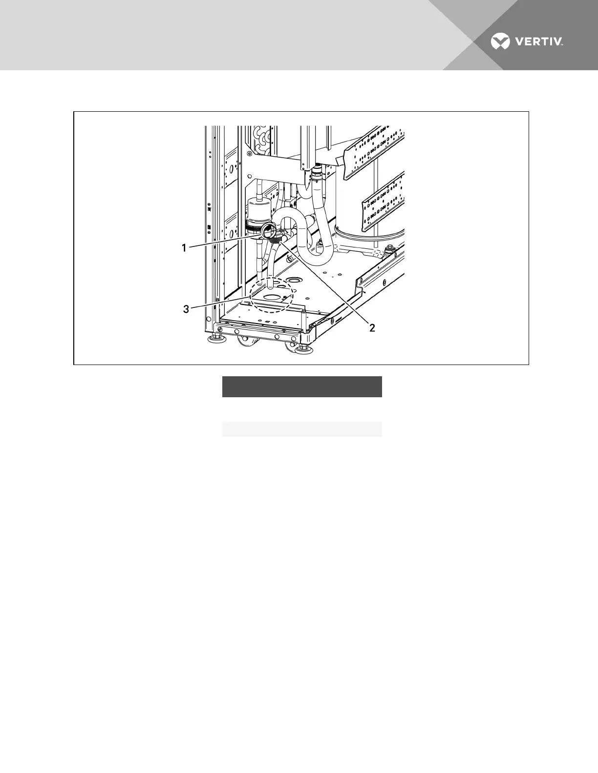
Figure 6.11 Condensate-pump drain piping, Air-cooled, 300-mm (12-in.)
ITEM DESCRIPTION
1
Bushing for bottom condensate exit
(field-installed in drain-line knockout hole)
2 Hose barb (field installed)
3 Drain-line knockout
Connecting Discharge Hose onWater/Glycol-cooled,300-mm(12-in.)Models
The 300-mm(12-in.) water/glycol-cooled units have separate models for top and bottom fluid
connections. Both have a factory-installed top discharge for the condensate-pump drain connection. The
discharge can be changed to the bottom of the unit in the field.
The unit has a 3/8-in.IDx5/8-in.OD vinyl, drain hose on the condensate discharge with a factory-
installed 3/8-in hose barb. Refer to the figure for the condensate-pump components.
For field-connection to the drain piping, a factory-supplied 1/2-in. MPT x 3/8-in. hose-barb threaded
adapter is included.
For top discharge:
Connect the discharge tubing to the tubing exiting the top of the unit.
For bottom discharge, run the condensate drain through the bottom of the unit:
Refer to the following figure and:
1. Unbolt the fasteners that hold the condensate pump in the unit.
2. Unplug the fan wiring pin connectors from the fan control board and remove the fan control
board.
Vertiv | Liebert CRV Installer/User Guide | 63