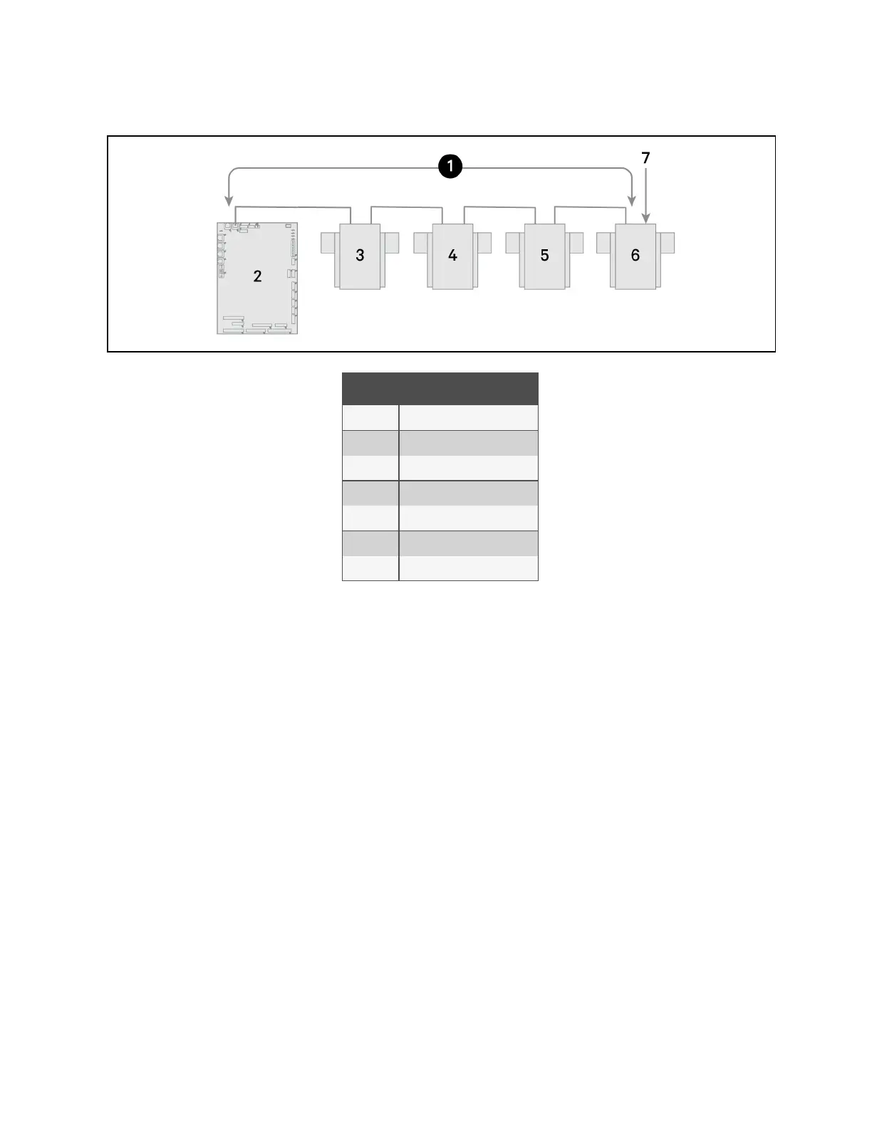
Figure 13.6 Example Sensor CANbus Arrangement
Item Description
1 CANbus communication loop
2 Liebert® iCOM™ control board
3 2T sensor
4 2T sensor
5 2T sensor
6 2T sensor
7 Terminated sensor
To terminate the last sensor:
1. Locate the sensor that will be last on the network.
NOTE: The last sensor on the network will be the sensor with only one CAN cable after all sensors are connected to
the CANbus network. See Connect the CANbus Cable and Ground on page191 .
2. Open the sensor’s case by removing the Phillips head screws (typically 3) on the rear of the housing to access
the jumper used for terminating.
3. Remove the black jumper from pins 1 and 2 on the P3 pin connector, and install it on pins 2 and 3 as shown in
Figure 13.7 on the next page .
4. Replace the sensor cover. The 2T sensor is terminated in the CANbus link.
13 Vertiv™ Liebert® iCOM™ Hardware Installation
187
Vertiv™ Liebert® iCOM™Installer/User Guide