M
A
IN BAY
CAN1
CAN2
MAIN BAY
CAN1
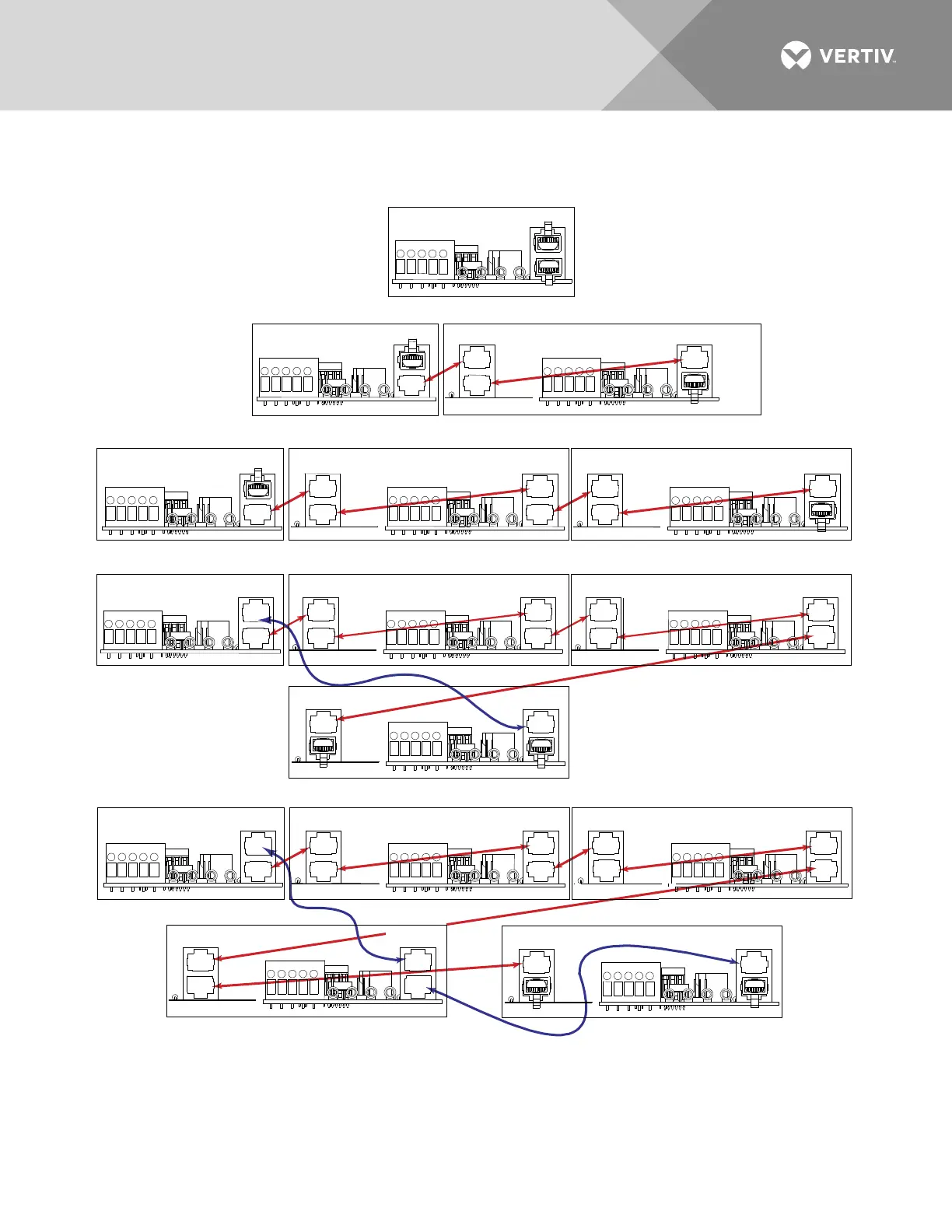
(5) BAY SYSTEM
RECT_CAN
OUT
SM_CAN
IN
OUT
IN
RECT_CAN
OUT
SM_CAN
IN
OUT
IN
RECT_CAN
OUT
SM_CAN
IN
OUT
IN
RECT_CAN
OUT
SM_CAN
IN
OUT
IN
RECT_CAN
OUT
SM_CAN
IN
OUT
IN
RECT_CAN
OUT
SM_CAN
IN
OUT
IN
RECT_CAN
OUT
SM_CAN
IN
OUT
IN
’’
NOTE: Use standard CAT5 communications cables.
MAIN BAY
CAN2
CAN1
MAIN BAY
CAN2
CAN1
SM_CAN
IN
OUT
RECT_CAN
MAIN BAY
CAN2
CAN1
RECT_CAN
OUT
SM_CAN
(1) BAY SYSTEM
(2) BAY SYSTEM
(3) BAY SYSTEM
(4) BAY SYSTEM
IN
OUT
IN
OUT
IN
RECT_CAN
OUT
SM_CAN
IN
OUT
IN
CAN2
SUPP BAY #1
SUPP BAY #1 SUPP BAY #2
SUPP BAY #1 SUPP BAY #2
SUPP BAY #1 SUPP BAY #2
SUPP BAY #3
SUPP BAY #3
SUPP BAY #4
1. Diagrams above are for typical configurations. CAN1 is used for all SM_CAN connections and for
RECT_CAN connecti
ons up through and including the bay with the 72nd rectifier slot maximum
(for 1R483500E3 or 1R484000E) or the 60th rectifier slot maximum (for 1R483500E).
CAN2 of the Main Bay should be connected to RECT_CAN IN in the supplementary bay that has the
73rd rectifier slot (for 1R483500E3 or 1R484000E) or the 61st rectifier slot (for 1R48500E).

 Loading...


